Epson Research and Development
Page 95
Vancouver Design Center
Hardware Functional Specification
S1D13504
Issue Date: 01/11/06
X19A-A-002-19
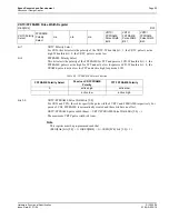
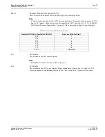
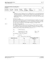
bit 7
VRTC Polarity Select
For CRTs, this bit selects the polarity of the VRTC. When this bit = 1, the VRTC pulse is active
high. When this bit = 0, the VRTC pulse is active low.
bit 6
FPFRAME Polarity Select
This bit selects the polarity of the FPFRAME for TFT and passive LCD. When this bit = 1, the
FPFRAME pulse is active high for TFT and active low for passive LCD. When this bit = 0, the
FRAME pulse is active low for TFT and active high for passive LCD.
bits 2-0
VRTC/FPFRAME Pulse Width Bits [2:0]
For CRTs and TFTs, these bits specify the pulse width of VRTC and FPFRAME respectively. For
passive LCDs, FPFRAME is automatically created and these bits have no effect.
VRTC/FPFRAME pulse width (lines) = VRTC/FPFRAME Pulse Width Bits [2:0] + 1.
The maximum VRTC pulse width is 8 lines.
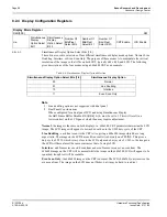
Note
This register must be programmed such that
(REG[0Ah] bits [5:0] + 1)
≥
(REG[0Bh] + 1) + (REG[0Ch] bits [2:0] + 1)
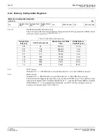
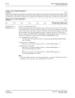
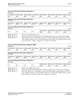
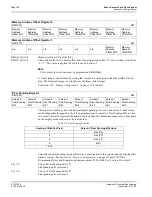
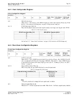
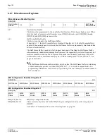
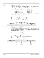
VRTC/FPFRAME Pulse Width Register
REG[0Ch]
RW
VRTC Polarity
Select
FPFRAME
Polarity
Select
n/a
n/a
n/a
VRTC/
FPFRAME
Pulse Width
Bit 2
VRTC/
FPFRAME
Pulse Width
Bit 1
VRTC/
FPFRAME
Pulse Width
Bit 0
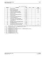
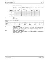
Table 8-5: FPFRAME Polarity Selection
FPFRAME Polarity Select
Passive LCD FPFRAME
Polarity
TFT FPFRAME Polarity
0
active high
active low
1
active low
active high

