Page 10
Epson Research and Development
Vancouver Design Center
S1D13504
Hardware Functional Specification
X19A-A-002-19
Issue Date: 01/11/06
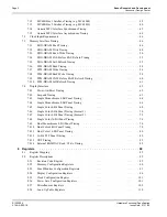
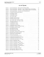
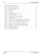
Figure 7-33: Dual Color 8-Bit Panel Timing . . . . . . . . . . . . . . . . . . . . . . . . . . . . . . . . . . . 78
Figure 7-34: Dual Color 8-Bit Panel A.C. Timing . . . . . . . . . . . . . . . . . . . . . . . . . . . . . . . . 79
Figure 7-35: Dual Color 16-Bit Panel Timing . . . . . . . . . . . . . . . . . . . . . . . . . . . . . . . . . . . 80
Figure 7-36: Dual Color 16-Bit Panel A.C. Timing . . . . . . . . . . . . . . . . . . . . . . . . . . . . . . . . 81
Figure 7-37: 16-Bit TFT Panel Timing . . . . . . . . . . . . . . . . . . . . . . . . . . . . . . . . . . . . . . 82
Figure 7-38: TFT A.C. Timing . . . . . . . . . . . . . . . . . . . . . . . . . . . . . . . . . . . . . . . . . . 83
Figure 7-39: CRT Timing . . . . . . . . . . . . . . . . . . . . . . . . . . . . . . . . . . . . . . . . . . . . . 85
Figure 7-40: CRT A.C. Timing . . . . . . . . . . . . . . . . . . . . . . . . . . . . . . . . . . . . . . . . . . 86
Figure 7-41: Generic Bus RAMDAC Read / Write Timing . . . . . . . . . . . . . . . . . . . . . . . . . . . . 88
Figure 9-1:
Display Buffer Addressing . . . . . . . . . . . . . . . . . . . . . . . . . . . . . . . . . . . . 113
Figure 10-1: 1/2/4/8 Bit-Per-Pixel Format Memory Organization . . . . . . . . . . . . . . . . . . . . . . . 115
Figure 10-2: 15/16 Bit-Per-Pixel Format Memory Organization . . . . . . . . . . . . . . . . . . . . . . . . 116
Figure 10-3: Image Manipulation . . . . . . . . . . . . . . . . . . . . . . . . . . . . . . . . . . . . . . . . 117
Figure 12-1: 1 Bit-Per-Pixel – 2-Level Gray-Shade Mode Look-Up Table Architecture . . . . . . . . . . . . 121
Figure 12-2: 2 Bit-Per-Pixel – 4-Level Gray-Shade Mode Look-Up Table Architecture . . . . . . . . . . . . 122
Figure 12-3: 4 Bit-Per-Pixel – 16-Level Gray-Shade Mode Look-Up Table Architecture . . . . . . . . . . . 122
Figure 12-4: 1 Bit-Per-Pixel – 2-Level Color Look-Up Table Architecture . . . . . . . . . . . . . . . . . . 123
Figure 12-5: 2 Bit-Per-Pixel – 4-Level Color Mode Look-Up Table Architecture . . . . . . . . . . . . . . . 124
Figure 12-6: 4 Bit-Per-Pixel – 16-Level Color Mode Look-Up Table Architecture . . . . . . . . . . . . . . 125
Figure 12-7: 8 Bit-Per-Pixel – 256-Level Color Mode Look-Up Table Architecture . . . . . . . . . . . . . . 126
Figure 14-1: Mechanical Drawing QFP15-128 . . . . . . . . . . . . . . . . . . . . . . . . . . . . . . . . . 129
Figure 14-2: Mechanical Drawing TQFP15-128 . . . . . . . . . . . . . . . . . . . . . . . . . . . . . . . . 130
Figure 14-3: Mechanical Drawing QFP20-144 . . . . . . . . . . . . . . . . . . . . . . . . . . . . . . . . . 131

