Page 12
Epson Research and Development
Vancouver Design Center
S1D13504
S5U13504B00C Rev. 2.0 PCI Evaluation Board User Manual
X19A-G-014-01
Issue Date: 2002/12/02
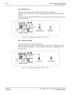
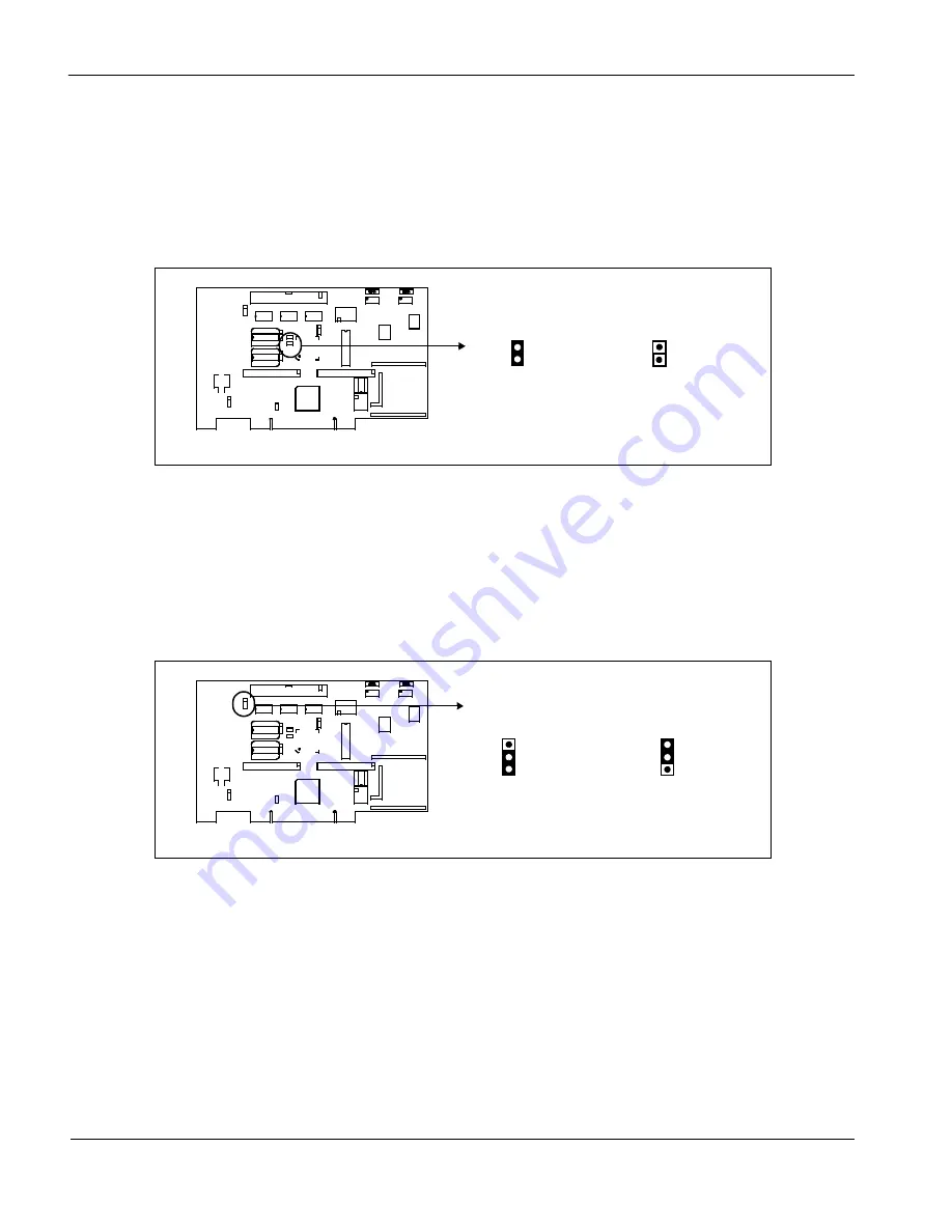
JP4 - IOVDD Current
JP4 allows the mesurement of S1D13504 IOVDD current consumption.
When the jumper is at position 1-2, the evaluation board is operating normally (default
setting).
When no jumper is installed, IOVDD current comsumption can be measured by connecting
an ampmeter to JP4.
Figure 3-5: Configuration Jumper (JP4) Location
JP5 - LCD Panel Voltage
JP5 selects the voltage level to the LCD panel.
When the jumper is at position 1-2, the LCD panel voltage level is configured for 5.0V.
When the jumper is at position 2-3, the LCD panel voltage level is configured for 3.3V
(default setting).
Figure 3-6: Configuration Jumper (JP5) Location
JP4
IOVDD
Normal
Operation
Measurement
JP5
+3.3 LCDVCC
+5V LCDVCC


