Page 68
Epson Research and Development
Vancouver Design Center
S1D13704
Programming Notes and Examples
X26A-G-002-03
Issue Date: 01/02/12
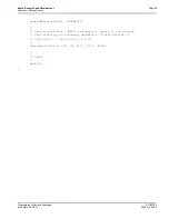
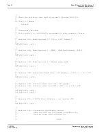
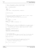
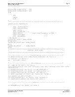
** - Set to maximum (i.e. 0x3FF). This register is used
** for split screen operation and should be set to 0
** during initialization.
*/
SET_REG(0x13, 0xFF);
SET_REG(0x14, 0x03);
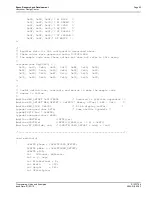
/*
** Look-Up Table
** In this example the LUT will be programmed in the register sequence.
** In practice the LUT would probably be done after the other registers.
*/
/*
** Register 15h - Look-Up Table Address
** - Set to 0 to start RGB sequencing at the first LUT entry.
*/
SET_REG(0x15, 0x00);
/*
** Register 16h - Look-Up Table Bank Select
** - Set all the banks to 0.
** - At 4BPP this makes no difference however it will affect
** appearance at other color depths.
*/
SET_REG(0x16, 0x00);
/*
** Register 17h - Look-Up Table Data
** - Write 16 RGB triplets to setup the LUT for 4BPP operation.
** - The LUT is 16 elements deep, 4BPP uses all the idices.
*/
pLUT = Color_4BPP;
for (LUTcount = 0; LUTcount < 16; L+)
{
for (RGBcount = 0; RGBcount < 3; R+)
{
SET_REG(0x17, *pLUT);
pLUT++;
}
}
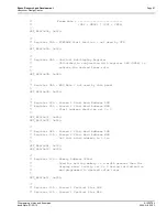
/*
** Register 18h - GPIO Configuration - set to 0
** - '0' configures the GPIO pins for input (power on default)
*/
SET_REG(0x18, 0x00);
/*
** Register 19h - GPIO Status - set to 0
** - This step has no reason other than it programs the GPIO
*

