Page 60
Epson Research and Development
Vancouver Design Center
S1D13704
Hardware Functional Specification
X26A-A-001-04
Issue Date: 01/02/08
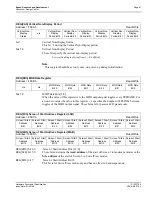
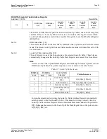
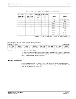
bits 4-0
FPLINE Start Position
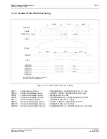
These bits are used in TFT/D-TFD mode to specify the position of the FPLINE pulse.
These bits specify the delay, in 8-pixel resolution, from the end of a line of display data
(FPDAT) to the leading edge of FPLINE. This register is effective in TFT/D-TFD mode
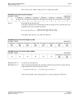
only (REG[01h] bit 7 = 1). This register is programmed as follows:
The following constraint must be satisfied:
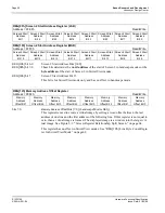
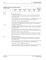
bits 4-0
Horizontal Non-Display Period
These bits specify the horizontal non-display period in 8-pixel resolution.
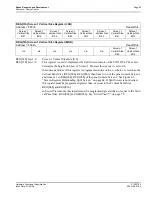
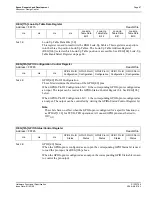
bits 5-0
FPFRAME Start Position
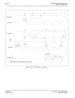
These bits are used in TFT/D-TFD mode to specify the position of the FPFRAME pulse.
These bits specify the number of lines between the last line of display data (FPDAT) and
the leading edge of FPFRAME. This register is effective in TFT/D-TFD mode only
(REG[01h] bit 7 = 1).
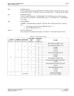
The contents of this register must be greater than zero and less than or equal to the Vertical
Non-Display Period Register, i.e.
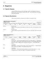
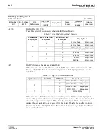
REG[07h] FPLINE Start Position
Address = FFE7h
Read/Write
n/a
n/a
n/a
FPLINE Start
Position Bit 4
FPLINE Start
Position Bit 3
FPLINE Start
Position Bit 2
FPLINE Start
Position Bit 1
FPLINE Start
Position Bit 0
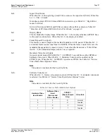
REG[08h] Horizontal Non-Display Period
Address = FFE8h
Read/Write
n/a
n/a
n/a
Horizontal
Non-Display
Period Bit 4
Horizontal
Non-Display
Period Bit 3
Horizontal
Non-Display
Period Bit 2
Horizontal
Non-Display
Period Bit 1
Horizontal
Non-Display
Period Bit 0
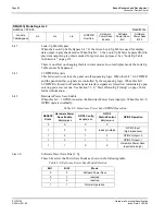
REG[09h] FPFRAME Start Position
Address = FFE9h
Read/Write
n/a
n/a
FPFRAME
Start Position
Bit 5
FPFRAME
Start Position
Bit 4
FPFRAME
Start Position
Bit 3
FPFRAME
Start Position
Bit 2
FPFRAME
Start Position
Bit 1
FPFRAME
Start Position
Bit 0
FPLINEposition pixels
(
)
REG 07h
[
]
2
+
(
)
8
×
=
REG 07h
[
]
REG 08h
[
]
≤
HorizontalNonDisplayPeriod pixels
(
)
REG 08h
[
]
4
+
(
)
8
×
=
FPFRAMEposition lines
(
)
REG 09h
[
]
=
1
REG 09h
[
]
REG 0Ah
[
]
≤
≤
*

