Page 42
Epson Research and Development
Vancouver Design Center
S1D13704
Programming Notes and Examples
X26A-G-002-03
Issue Date: 01/02/12
7.6 Examples
Example 6: Enable default SwivelView mode for a 320x240 panel at 4 bpp.
Before switching to SwivelView mode from landscape mode, display memory should be
cleared to make the user perceived transition smoother. Images in display memory are not
rotated automatically by hardware and the garbled image would be visible for a short period
of time if video memory is not cleared.
In this example we will bypass having to recalculate the horizontal and vertical non-display
times (frame rate) by selecting the default SwivelView mode scheme.
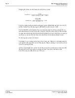
1. Calculate and set the Screen 1 Start Word Address register.
OffsetBytes = (Width x BitsPerPixel / 8) - 1 = (256 x 4 / 8) -1 = 127 = 007Fh
(“Width” is the width of the SwivelView mode display - in this case the next power of
two greater than 240 pixels or 256.)
Set Screen1 Display Start Word Address LSB (REG [0Ch]) to 7Fh and Screen1 Dis-
play Start Word Address MSB (REG[0Dh]) to 00h.
2. Calculate the Line Byte Count
The Line Byte Count also must be based on the power of two width.
LineByteCount = Width x BitsPerPixel / 8 = 256 x 4 / 8 = 128 = 80h.
Set the Line Byte Count (REG[1C]) to 80h.
3. Enable SwivelView mode.
This example uses the default SwivelView mode scheme. If we do not change the
SwivelView Mode Pixel Clock Select bits then we will not have to recalculate the non-
display timings to correct the frame rate.
Write 80h to the SwivelView Mode Register (REG[1Bh]).
The display is now configured for SwivelView mode use. Offset zero into display memory
will corresponds to the upper left corner of the display. The only thing to keep in mind is
that the count from the first pixel of one line to the first pixel of the next line (refered to as
the "stride") is 128 bytes.
*

