background image


Rev. 1.0 

S1D13C00 

S5U13C00P01C100 Customer 

Development Board User 

Manual 


Document Number: XB8A-G-001-01.0 


Summary of Contents for S1D13C00

Page 1: ...Rev 1 0 S1D13C00 S5U13C00P01C100 Customer Development Board User Manual Document Number XB8A G 001 01 0 ...

Page 2: ...out notice Seiko Epson does not assume any liability of any kind arising out of any inaccuracies contained in this material or due to its application or use in any product or circuit and further there is no representation that this material is applicable to products requiring high level reliability such as medical products Moreover no license to any intellectual property rights is granted by impli...

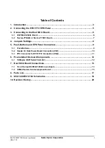
Page 3: ... 4 Jumpers Settings 8 5 Push Buttons and EPD Panel Connectors 9 5 1 Push Buttons 9 5 2 Header for Hulk Power Board Connection CN1 10 5 3 FPC Connector for ET011TT2 Connection CN2 11 6 Pre installed On board Components 12 6 1 16Mbytes QSPI Serial Flash U2 12 7 Host MCU Board Connections 13 7 1 Tiva C Series EK TM4C1294XL Launchpad 13 7 2 STM32 Nucleo 144 development board 15 8 Parts List 17 9 S5U13...

Page 4: ...ii Seiko Epson Corporation S5U13C00P01C100 Board User Manual Rev 1 0 ...

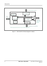
Page 5: ... EPD Evaluation Board consists of A S1D13C00 Memory Display Controller U1 Four 2x10 connectors for Host Interface connection J4 J5 J6 and J7 and 5V 3 3V power A 16Mbytes QSPI Serial Flash U2 A flexible printed circuit FPC connector CN2 for connecting to a ET011TT2 EPD panel An 18 pin right angle header connector for connecting to other panels Figure 1 1 shows the block diagram of S5U13C00P01C100 f...

Page 6: ...1 S5U13C00P01C100 Block Diagram for Interface Regulator Host interface Memory display interface HULK power board interface ET011TT2 panel module interface S1D13C00 Serial Flash Through holes Booster Components CN1 C N 2 Booster components are part of booster circuits of ET011TT2 panel module ...

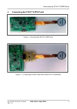
Page 7: ... EPD Panel S5U13C00P01C100 Board User Manual Seiko Epson Corporation 5 Rev 1 0 2 Connecting the ET011TT2 EPD Panel Figure 2 Connecting the ET011TT2 EPD Panel Figure 2 1 Connecting the HULK Power Board with ET011TT2 EPD Panel ...

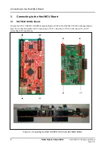
Page 8: ...d 3 1 EK TM4C1294XL Board Position the S5U13C00P01C100 EPD Evaluation Board on TOP of the EK TM4C1294XL Launchpad Board press the two boards together with J4 connecting to X8 J5 connecting to X9 J6 connecting to X6 and J7 connecting to X7 respectively Figure 3 Connecting the S5U13C00P01C100 to the EK TM4C1294XL J4 J5 J6 J7 X8 X9 X6 X7 ...

Page 9: ...oration 7 Rev 1 0 3 2 Nucleo F746ZG or Nucleo F767ZI Board First connect the S5U13C00M00C100 adapter board to the Nucleo board Second connect the S5U13C00P01C100 board to the S5U13C00M00C100 adapter board Figure 3 1 Connecting the S5U13C00P01C100 to the Nucleo F746ZG or Nucleo F767ZI ...

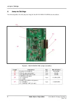
Page 10: ...S5U13C00P01C100 Jumpers Locations Jumpers Descriptions Type Default Position JP2 External VC3 Connection 2 pin Not installed JP3 VDD_IC supply series jumper 2 pin Installed JP4 VDD_EPD supply series jumper 2 pin Installed JP6 DISPVDD source supply 1 2 VDD_EPD 2 3 VMDL 3 pin 1 2 VDD_EPD JP7 HIFCNF host interface configuration 1 2 SPI QSPI 2 3 INDIRECT 8 BIT not used 3 pin 1 2 SPI QSPI JP2 JP3 JP4 J...

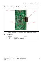
Page 11: ...anual Seiko Epson Corporation 9 Rev 1 0 5 Push Buttons and EPD Panel Connectors Figure 5 S5U13C00P01C100 Push Buttons and EPD Panel Connector Locations 5 1 Push Buttons Push Button Description SW1 Reset button SW2 User button connected to P01 port pin CN1 SW1 SW2 CN2 ...

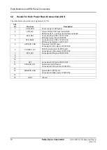
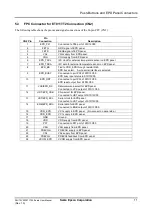
Page 12: ...RST Connected to port P03 of S1D13C00 EPD reset output from S1D13C00 4 EPD_BUSY Connected to port P02 of S1D13C00 EPD busy input status to S1D13C00 5 HST EPD_CSB Chip select for EPD panel Connected to HST output of S1D13C00 6 VCK EPD_DC Data command select for EPD panel Connected to VCK output of S1D13C00 7 EPD_P51 Connected to P06 port of S1D13C00 8 9 10 11 P07 Connected to P07 port of S1D13C00 1...

Page 13: ...face is selected 9 EPD_BUSY Connected to port P02 of S1D13C00 EPD busy input status to S1D13C00 10 EPD_RST Connected to port P03 of S1D13C00 EPD reset output from S1D13C00 11 VCK EPD_DC Data command select for EPD panel Connected to VCK output of S1D13C00 12 HST EPD_CSB Chip select for EPD panel Connected to HST output of S1D13C00 13 VST EPD_SCL Serial clock for EPD panel Connected to VST output o...

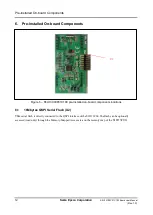
Page 14: ...n board Components Figure 6 S5U13C00P01C100 pre installed on board components locations 6 1 16Mbytes QSPI Serial Flash U2 This serial flash is directly connected to the QSPI interface of the S1D13C00 The flash can be optionally accessed read only through the Memory Mapped Access area on the memory map of the S1D13C00 U2 ...

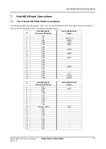
Page 15: ...C100 Customer Development Board J4 EK TM4C1294XL Connector X8 Signals S5U13C00P01C100 Signal 1 3V3 2 5V HOST_5V 3 PE4 HIFD0 4 GND GND 5 PC4 HIFD7 6 PE0 7 PC5 HIFD6 8 PE1 9 PC6 HIFD5 10 PE2 11 PE5 HIFD1 12 PE3 13 PD3 14 PD7 15 PC7 HIFD4 16 PA6 17 PB2 18 PM4 P11 19 PB3 HIFRD 20 PM5 HIFIRQ J5 EK TM4C1294XL Connector X9 Signals S5U13C00P01C100 Signal 1 PF1 2 GND GND 3 PF2 4 PM3 5 PF3 6 PH2 7 PG0 8 PH3...

Page 16: ... 5V HOST_5V 3 PD2 4 GND GND 5 PP0 6 PB4 HIFDE 7 PP1 8 PB5 HIFWR 9 PD4 HIFD2 10 PK0 11 PD5 HIFD3 12 PK1 13 PQ0 14 PK2 15 PP4 16 PK3 17 PN5 18 PA4 19 PN4 20 PA5 J7 EK TM4C1294XL Connector X7 Signals S5U13C00P01C100 Signal 1 PG1 2 GND GND 3 PK4 4 PM7 5 PK5 6 PP5 7 PM0 8 PA7 9 PM1 10 TARGET_RST 11 PM2 12 PA3 PQ2 13 PH0 14 PA2 PQ3 15 PH1 16 PP3 HIFCS 17 PK6 18 PQ1 19 PK7 20 PM6 ...

Page 17: ...D0 J4 4 GND GND CN7 8 Ground J4 5 HIFD7 PE10 CN10 24 Host INDIRECT8 D7 J4 6 J4 7 HIFD6 PE9 CN10 4 Host INDIRECT8 D6 J4 8 J4 9 HIFD5 PE8 CN10 18 Host INDIRECT8 D5 J4 10 J4 11 HIFD1 PD12 CN10 21 Host SPI QSPI D1 J4 12 J4 13 J4 14 J4 15 HIFD4 PE7 CN10 20 Host INDIRECT8 D4 J4 16 J4 17 J4 18 J4 19 HIFRD PD4 CN9 8 Host INDIRECT8 read signal J4 20 HIFIRQ PB1 CN10 7 Interrupt request to host S5U13C00P01C1...

Page 18: ...HIFDE PB6 CN10 13 Host device enable signal J6 7 J6 8 HIFWR PB2 CN10 15 Host SPI QSPI clock J6 9 HIFD2 PE2 CN10 25 Host SPI QSPI D2 J6 10 J6 11 HIFD3 PD13 CN10 19 Host SPI QSPI D3 J6 12 J6 13 J6 14 J6 15 J6 16 J6 17 J6 18 J6 19 J6 20 S5U13C00P00Cx00 Board STM32 Nucleo 144 development board Description Signal Signal J7 1 J7 2 GND GND CN10 5 Ground J7 3 J7 4 J7 5 J7 6 J7 7 J7 8 J7 9 J7 10 J7 11 J7 1...

Page 19: ...Hirose HIF3H 20DA 2 54DSA 71 15 1 J8 Not mounted CONN HEADER 18POS 2x9 0 1 Hirose A1 18PA 2 54DSA 71 16 1 J9 Not mounted CONN HEADER 4POS 0 1 Honda Tsushin FFC 52AMEP1 4P 17 1 J10 Not mounted CONN HEADER 2POS 0 1 Honda Tsushin FFC 52AMEP1 2P 18 1 LED1 LED 3 3V Green LED GREEN DIFFUSED 1608 SMD Stanley Electric BG1111C TR 19 1 L1 10uH 10uH 510mA 540mOhm wirewound inductor Taiyo Yuden NR3010T100M 20...

Page 20: ...S5U13C00P01C100 Schematics 18 Seiko Epson Corporation S5U13C00P01C100 Board User Manual Rev 1 0 9 S5U13C00P01C100 Schematics S5U13C00P01C100 Schematics 1 of 2 ...

Page 21: ...S5U13C00P01C100 Schematics S5U13C00P01C100 Board User Manual Seiko Epson Corporation 19 Rev 1 0 S5U13C00P01C100 Schematics 2 of 2 ...

Page 22: ...Revision History 20 Seiko Epson Corporation S5U13C00P01C100 Board User Manual Rev 1 0 10 Revision History Rev No Date Page Category Contents 1 0 23 01 2019 Released as Rev 1 0 ...

Page 23: ...ion on the S1C13C00 and other Epson Display Controllers visit the Epson Global website https global epson com products_and_drivers semicon products display_controllers For Sales and Technical Support contact the Epson representative for your region https global epson com products_and_drivers semicon information support html ...

Reviews: