


S1F76300 Series
4–16
EPSON
S1F70000 Series
Technical Manual
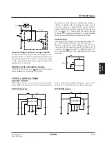
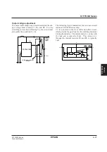
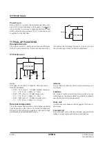
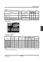
Inductor
Use an inductor with low direct-current resistance and
low losses.
Leadless
Pre-wound, leadless inductors using surface-mount
technology are the most suitable for portable equipment
and other space-critical applications.
Drum coil
Avoid using drum coils because their magnetic field
can induce noise.
Toroidal coil
Use a toroidal coil to virtually eliminate magnetic field
leakage, reduce losses and improve performance.
Diode
Use a Schottky barrier diode with a high switching
speed and low forward voltage drop, V
F
.
Capacitor
To minimize ripple voltages, use a capacitor with a
small equivalent direct-current resistance for smooth-
ing.
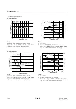
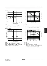
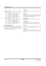
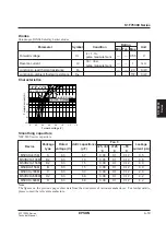
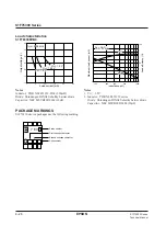
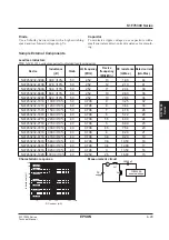
Notes
■
100
µ
H
≤
L
≤
1mH, C
≤
10
µ
F, D = Schottky diode
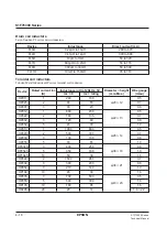
■
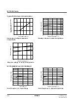
S1F76310M1A0
• Peff = 70% when L = 220
µ
H (leadless inductor),
V
I1
= 1.5V,
f
CLK
= 32kHz, I
O
= 4mA
• Peff = 75% when L = 220
µ
H (drum coil),
V
I1
= 1.5V,
f
CLK
= 32kHz, I
O
= 6mA
• Peff = 80% when L = 300
µ
H (toroidal coil),
V
I1
= 1.5V,
f
CLK
= 32kHz, I
O
= 7mA
■
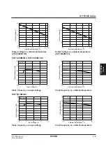
S1F76310M1B0
• Peff = 70% when L = 220
µ
H (leadless inductor),
V
I1
= 1.5V,
f
CLK
= 32kHz, I
O
= 8mA
• Peff = 75% when L = 220
µ
H (drum coil),
V
I1
=1.5V,
f
CLK
= 32kHz, I
O
= 9mA
• Peff = 80% when L = 300
µ
H (toroidal coil),
V
I1
= 1.5V,
f
CLK
= 32kHz, I
O
= 10mA
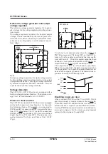
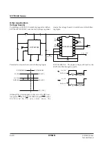
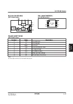
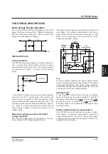
External components
The performance characteristics of switching regulators
depend greatly on the choice of external components.
Observing the following guidelines will ensure high
performance and maximum efficiency.
Summary of Contents for S1F76610C0B0
Page 4: ...S1F70000 Series Technical Manual ...
Page 17: ...1 DC DC Converter ...
Page 43: ...2 DC DC Converter Voltage Regulator ...
Page 107: ...3 Voltage Regulator ...
Page 145: ...4 DC DC Switching Regulators ...
Page 200: ...5 Voltage Detector ...
Page 223: ...6 Appendix ...


