S1R72803F00A
EPSON
89
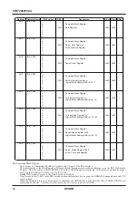
Address Register Name
Bit Symbol
R/W
Description
H.Rst S.Rst B.Rst
0x200001 FlashCtlCnt_H
7:
0:
1:
6:
0:
1:
5: FlashCtlCnt[21]
4: FlashCtlCnt[20]
IF(FlashChipErs==1 && FlashSctErs==0 &&
0x00
0x00
–
3: FlashCtlCnt[19]
FlashWrEnb==0){
2: FlashCtlCnt[18]
R/W Enable;
1: FlashCtlCnt[17]
Default Value = 0x3FFFFF;
0: FlashCtlCnt[16]
}
0x200002 FlashCtlCnt_M
7: FlashCtlCnt[15]
erase if(FlashChipErs==0 && FlashSctErs==1 &&
6: FlashCtlCnt[14]
FlashWrEnb==0){
5: FlashCtlCnt[13]
R/W Enable;
4: FlashCtlCnt[12]
R/W
Default Value = 0x0FFFFF;
0x00
0x00
–
3: FlashCtlCnt[11]
}
2: FlashCtlCnt[10]
erase if(FlashChipErs==0 && FlashSctErs==0 &&
1: FlashCtlCnt[9]
FlashWrEnb==1){
0: FlashCtlCnt[8]
R/W Enable;
0x200003 FlashCtlCnt_L
7: FlashCtlCnt[7]
Default Value = 0x000190;
6: FlashCtlCnt[6]
} else {
5: FlashCtlCnt[5]
Read is alway Zero;
4: FlashCtlCnt[4]
Write is Ignore;
0x00
0x00
–
3: FlashCtlCnt[3]
}
2: FlashCtlCnt[2]
1: FlashCtlCnt[1]
0: FlashCtlCnt[0]
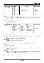
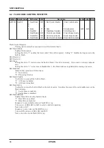
Flash Control Count Register
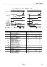
This register is enabled when the FlashChipErs bit, FlashSctErs bit or FlashWrEnb bit of the FlashCtl Register
is set alone. It is disabled when two or more bits are set.
When setting them in the unit of byte, conform to the order of FlashCtlCnt_H (higher order byte), FlashCtlCnt_M,
and FlashCtlCnt_L (lower order byte). On completion of writing to the lower order byte, setting of this register
is enabled.
Pulse width (Default value)
FlashChipErs: 40ns x 0x3FFFFF = 167.8ms
FlashSctErs:
40ns x 0x0FFFFF = 41.9ms
FlashWrEnb: 40ns x 0x000190 = 16.0
µ
s


