S1D13517 Display Controller
S5U13517P00C100 Evaluation Board User Manual (Rev. 1.0)
EPSON
9
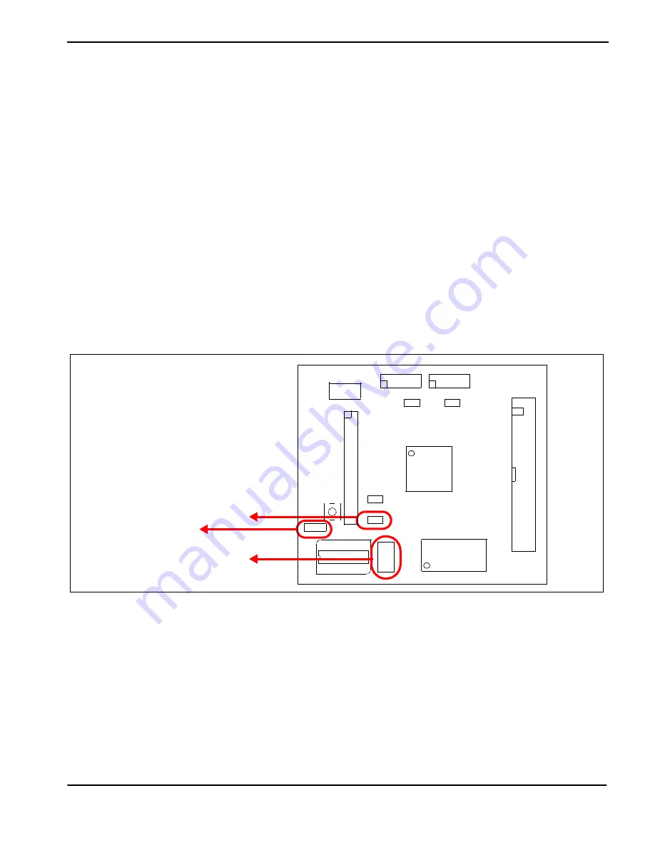
J4 - IOVDD Source
J4 is used to select the source for the IOVDD supply voltage.
When the jumper is at position 1-2, the IOVDD voltage is provided by the 3.3V power supply of the board.
When the jumper is at position 2-3, the IOVDD voltage must be provided to the CN1 connector, pin 32.
J5 - 24MHz Control
J5 is used to control the 24MHz oscillator.
When no jumper is installed, the 24MHz oscillator is running.
When the jumper is at position 1-2, the 24MHz oscillator is stopped.
J6 - Clock Source
J6 is used to select the source for the clock input.
When the jumper is at position 1-2, the on board 24MHz oscillator is selected.
When the jumper is at position 3-4, the second oscillator is selected.
When the jumper is at position 5-6, the CLKI pin is forced to GND.
Figure 3-3: Configuration Jumper Location (J4, J5, J6)
J4
J5
J6


