Page 8
Epson Research and Development
Vancouver Design Center
S1D13506
S5U13506P00C100 PCI Evaluation Board User Manual
X25B-G-014-02
Issue Date: 2009/03/02
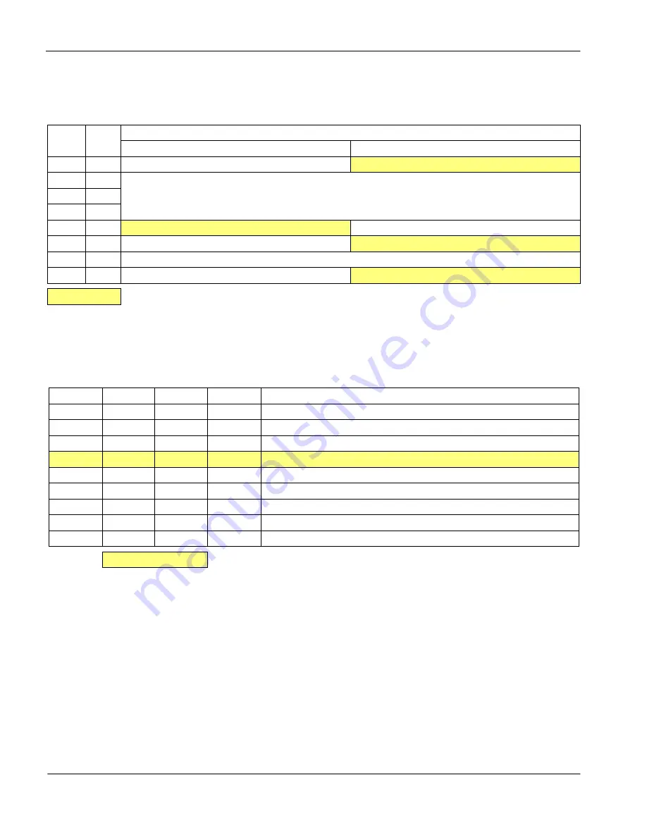
The following DIP switch settings configure the S1D13506.
The following table shows the Host Bus Interface options available. The host bus interface
is selected according to the evaluation platform to be used.
Table 3-1: Configuration DIP Switch Settings
Switch Signal
Value of this pin at rising edge of RESET# is used to configure:
Closed/On=1
Open/Off=0
S1-1
MD15
WAIT# is always driven.
WAIT# is tristated when S1D13506 is not selected
S1-2
MD1
See Table 3-2:, “Host Bus Interface Selection” on page 8
S1-3
MD2
S1-4
MD3
S1-5
MD4
Little Endian
Big Endian
S1-6
MD5
WAIT# is active high
WAIT# is active low
S1-7
MD11
See Table 3-2:, “Host Bus Interface Selection” on page 8
S1-8
MD12
BUSCLK input divided by 2
BUSCLK input not divided
= Required configuration when used in a PCI environment
Table 3-2: Host Bus Interface Selection
MD11
MD3
MD2
MD1
Host Bus Interface
0
0
0
0
SH-4/SH-3
0
0
0
1
MC68K Bus 1
0
0
1
0
MC68K Bus 2
0
0
1
1
Generic
0
1
0
0
Reserved
0
1
0
1
MIPS/ISA
0
1
1
0
PowerPC
0
1
1
1
PC Card
1
1
1
1
Philips PR31500/PR31700 / Toshiba TX3912
= Required configuration when used in a PCI environment


