background image

1  Overview

S5U1C17001H USER MANUAL


Seiko Epson Corporation 

(ICDMINI VER1.0 and VER1.1)

1  Overview

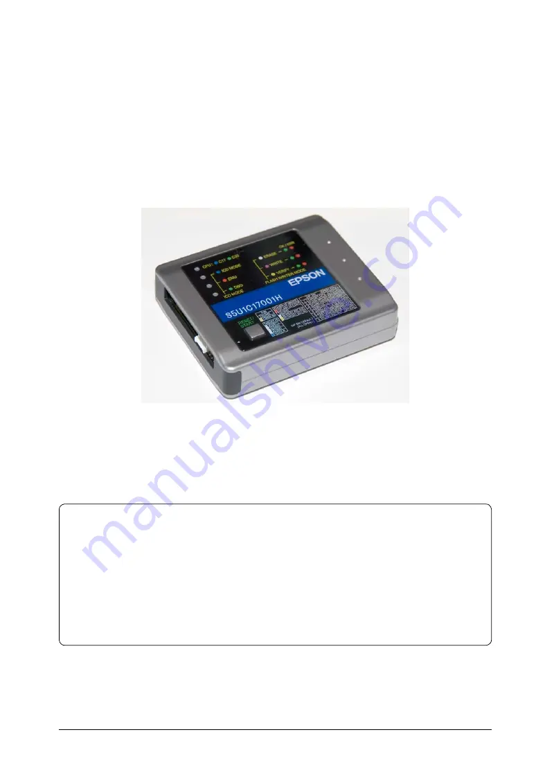
The S5U1C17001H (ICDmini) is a hardware tool (emulator) that allows software to be efficiently developed for the 
S1C17 Family of 16-bit processors*. The S5U1C17001H provides a software development environment with the 
debugger (gdb.exe) by communicating it to the S1C17 processor on the target system and the debugger. In addition 
to debugging, it can be used as a Flash programmer to program the Flash memory built into the S1C17 processor 
on the target system as flash writer at main unit.
This  manual  primarily  explains  how  to  use  the  S5U1C17001H.  For  details  on  the  debugger  functions  and 
commands,  refer  to  the  “Debugger”  section  in  the  “S5U1C17001C  Manual  (C  Compiler  Package  for  S1C17 
Family).”

S5U1C17001H External View

Note:  Do not open the case as it may cause a malfunction.

This manual is for the following 2 models.
 

• S5U1C17001H1100 (ICDmini ver1.0)


• S5U1C17001H1200 (ICDmini ver1.1)

* Through firmware update, support is also expected for the S1C33 family 32-bit processor.

Precautions before using the S5U1C17001H

Please read the sections shown below before getting started with the S5U1C17001H. These sections, especially (2) 
and (3), describe the answers to frequently asked questions.

(1)  Chapter 2, Components Included with Package
 

Make sure all of the listed items are included with your package.

(2)  Section 4.2, Connecting to the Host Computer
 

Install the USB driver before the S5U1C17001H can be used.

(3)  Section 4.1, Connecting the Target System
 

Please pay particular attention to the Notes.

Summary of Contents for S5U1C17001H

Page 1: ...Rev 1 2 CMOS 16 BIT SINGLE CHIP MICROCONTROLLER S5U1C17001H User Manual ICDmini Ver1 0 and Ver1 1 ...

Page 2: ...hing made in accordance with this material will be free from any patent or copyright infringement of a third party This material or portions thereof may contain technology or the subject relating to strategic products under the control of the Foreign Exchange and Foreign Trade Law of Japan and may require an export license from the Ministry of Economy Trade and Industry or other approval from anot...

Page 3: ... not fixed Specification Package D die form F QFP B BGA Model number Model name C microcomputer digital products Product classification S1 semiconductor Development tools S5U1 C 17000 H2 1 Packing specifications 00 standard packing Version 1 Version 1 Tool type Hx ICE Dx Evaluation board Ex ROM emulation board Mx Emulation memory for external ROM Tx A socket for mounting Cx Compiler package Sx Mid...

Page 4: ... the Host Computer 11 5 ICD Mode 13 5 1 Specifying ICD Mode 13 5 2 Activation in ICD Mode 13 5 2 1 When the TARGET RST OUT Signal is Not Connected 13 5 2 2 When the TARGET RST OUT Signal is Connected 14 5 3 Starting Up the Debugger 14 5 4 Connection Test 14 6 Flash Programmer Mode 15 6 1 Preparation for Flash Programming 15 6 2 Operations in Flash Programmer Mode 15 7 Firmware Update 17 8 Precauti...

Page 5: ...the debug functions depending on the ICD cannot be used This is the mode to debug the target program using the S5U1C17001H ICDmini or ICD board The program will be executed on the target board The S5U1C17001H ICDmini must be used in this mode Target S1C17xxx Normal mode Debug mode The normal mode is the normal state while the target is executing the user program The target enters debug mode by one...

Page 6: ...ommands refer to the Debugger section in the S5U1C17001C Manual C Compiler Package for S1C17 Family S5U1C17001H External View Note Do not open the case as it may cause a malfunction This manual is for the following 2 models S5U1C17001H1100 ICDmini ver1 0 S5U1C17001H1200 ICDmini ver1 1 Through firmware update support is also expected for the S1C33 family 32 bit processor Precautions before using th...

Page 7: ...DCLK frequency to communicate with the target 4 kHz to 40 MHz 2 Flash programming power voltage supply Available Target reset signal output Available Target system I O interface voltage 3 3 V 1 8 V or voltage Ver1 0 1 0 to 5 0V Ver1 1 1 0 to 5 5V input from the target Target system interface connector 4 pin connector Flash programming power supply connector 4 pin connector 1 Scheduled to be suppor...

Page 8: ...pecified below are not included with the package These items must be prepared separately 9 S5U1C17001H User Manual ICDmini Ver 1 0 1 1 this PDF downloadable from the SEIKO EPSON HP When developing an S1C17 application 10 Debugger gdb exe for the S1C17 Family included in the S1C17 Family C Compiler Package 11 Manual for the S1C17 family debugger included in the C compiler manual of the S1C17 family...

Page 9: ... signal interface See Section 4 1 2 Flash Programming Power Supply Connector for the pin assignment and connection Note The S5U1C17001H is equipped with a 7 V Flash programming power supply with output capacities of 30mA Note however that its usage depends on the S1C processor Be sure to avoid using this power supply for the S1C processor do not set SW8 of the DIP switch to ON if its technical man...

Page 10: ...le 3 1 5 SW7 Settings SW7 Setting OPEN h OFF default ON i ON When SW7 is set to ON a connection between the S5U1C17001H and the debugger can be established even if a target is not connected See Chapter 7 Firmware Update for how to update the firmware Enabling voltage output for Flash programming SW8 Table 3 1 6 SW8 Settings SW8 Setting OPEN h OFF default ON i ON Note The S5U1C17001H is equipped wi...

Page 11: ...er Especially if supplying the flash programming voltage either connect directly to the host computer s USB port or use an AC adapter with USB 5 V output capable of supplying power to the USB cable If using an AC adapter set the S5U1C17001H mode to be used and confirm beforehand that erasing and writing is possible as desired 3 3 Top Panel Top Panel LED1 LED4 The four LEDs located on the top panel...

Page 12: ...G This LED indicates that the target S1C processor is placed in debug mode l green The target S1C processor is placed in debug mode Also this LED rights with LED3 before the initial connection between the S5U1C17001H and the target S1C processor has been established l out Other In Flash programmer mode When the S5U1C17001H starts up in Flash programmer mode LED2 lights in white LED3 lights in mage...

Page 13: ...for connecting with the S1C processor on the target system If the target board has not been connected physically the S5U1C17001H enters initial connection waiting status When the TARGET RST OUT signal of the S5U1C17001H has been connected to the target system a reset signal is output to the target system simultaneously In Flash programmer mode Click The S5U1C17001H starts the selected Flash operat...

Page 14: ...g to the target system before connecting the target system The signals connected to the S5U1C17001H are very high speed signals so the connector on the target system must be mounted within 5cm from the S1C processor If there is more distance between the connector and the S1C processor the S5U1C17001H may not work properly When wiring the S1C processor to the target connector for connecting the S5U...

Page 15: ...formed more efficiently When using the Flash protection function it is best to have a connection Connection is also recommended in the Flash programmer mode and when using the S5U1C17001H as the Gang Writer Gang Programmer using S5U1C17000Y2 S5U1C17001H TARGET RST OUT Target system S1C processor Pull up resistor Reset switch Reset circuit on the target system RESET 4 3 2 1 Figure 4 1 2 1 Example o...

Page 16: ...er Especially if supplying the flash programming voltage either connect directly to the host computer s USB port or use an AC adapter with USB 5 V output capable of supplying power to the USB cable If using an AC adapter set the S5U1C17001H mode to be used and confirm beforehand that erasing and writing is possible as desired 3 3 Top Panel Top Panel LED1 LED4 The four LEDs located on the top panel...

Page 17: ...ion S5U1C17001H User Manual ICDMini Ver1 0 and ver1 1 The device manager will be displayed as shown below when the USB driver has been installed correctly Note If the window above is not displayed correctly try to reinstall the USB driver ...

Page 18: ...he TARGET RST OUT Signal is Not Connected When the TARGET RST OUT signal is not connected to the reset input on the target system start up the S5U1C17001H by the procedure described below 1 Hold down the RESET START switch on the S5U1C17001H LED1 white LED2 white LED3 white LED4 l out 2 Hold down the reset switch on the target system 3 Release the RESET START switch on the S5U1C17001H LED1 l blue ...

Page 19: ...tablished by the operations described above When debugging using the debugger with the S5U1C17001H connected the debugger must be set to ICD Mini mode by executing the target command gdb target icd usb f Command to set the debugger in ICD Mini mode For the debug commands and how to operate the debugger refer to the S5U1C17001C Manual C Compiler Package for S1C17 Family When gdb target sim is execu...

Page 20: ...del 17701 fls fwr17701v11 saf 0x48 0x80 A Flash erase write program for the Mini target S1C processor or external Flash memory must be saved in the ICDmini For details of the Flash erase write program refer to the readme file below following installation of GNU17 C EPSON GNU17 mcu_model xxxxx fls Default installation 4 Save the user program for writing to the target Flash memory in the ICDmini wit...

Page 21: ...he target system including the Flash to be programmed to the S5U1C17001H 4 Press the RESET START switch The S5U1C17001H starts the selected Flash operation The LED indicates the operation being executed During erasing During programming During verification l ERASE blinking in white l WRITE W blinking in magenta l VERIFY W blinking in yellow 5 When the Flash operation has finished the LED lights as...

Page 22: ...t C cd EPSON gnu17 gdb 4 Enter the commands shown below when debugger starts up gdb target icd usb After entering the commands the following will be displayed C17 ICD17 debugging Connecting with target ID_OK done ICD Initializing ICD_INITALIZE done Read ICD Version ICD_VER_READ done ICDmini hardware version 1 0 ICDmini software version 1 1 f The current firmware version Debug base address ID_DATA_...

Page 23: ...SET START switch to restart the S5U1C17001H After completing the operation and the LEDs are as follows LED1 l blue or l green LED2 l red LED3 l red LED4 l red or after pressing and releasing the RESET START switch if the LEDs are as follows LED1 white LED2 white LED3 white LED4 l out the firmware update may have failed for some reason If a malfunction occurs during a firmware update and the S5U1C1...

Page 24: ...an interrupt received in other parts of the program is paused as with the STEP command The interrupt that has been paused is serviced immediately before the target program is executed or immediately after one instruction is executed after the debugger gdb exe on the host computer has directed that the target program be executed For details on single step execution STEP and NEXT refer to the Debugg...

Page 25: ...ess Refer to the technical manual of each model for the TTBR value 8 3 Notes on Use of S5U1C17001H Powering on off After turning off the power to the S5U1C17001H by disconnecting the USB cable wait at least 10 seconds before turning the power on connecting the USB cable again If the power is turned on immediately after it is turned off the S5U1C17001H may not be initialized correctly in a power on...

Page 26: ...ither removing the 33 W resistor to reduce noise and other problems or pulling this line up to the VDD level S1C processor DCLK GND DSIO DST2 Target connector Within 5 cm Place a 33 Ω resistor in series at a location as close to the S1C processor as possible Figure 8 3 1 Wiring between S1C Processor and Target Connector Reset request Do not reset the target system while the target program executio...

Page 27: ... Section 5 2 Activation in ICD Mode and start up in the correct order The following message suddenly appears while the target program is being executed by the debugger gdb exe in the host computer Break by external break Program received signal SIGINT Interrupt This problem is caused by low level noise on the DSIO signal of the target system or when the BRK IN pin goes GND level 1 Is the target sy...

Page 28: ... Target system interface cable 4 pins Length Approx 15 cm Flash programming power supply cable 4 pins Length Approx 15 cm Table 10 2 Recommended Connectors on the Target System Components Items Specifications Remarks Target system interface connector 4 pins Connector 4 pin straight A2 4PA 2 54DS 71 HRS Flash programming power supply connector 4 pins Connector 4 pin L angle S04B PASK 2 JST Table 10...

Page 29: ...tly speaking if a Low signal is input continuously the output from DST2 is as follows DST2 If DST2 pin output pin does not change from Low to High check the hardware of the target board Step 2 Try to establish a connection with the ICDmini 1 Set the DIP switches of the ICDmini The default is all open Set the switches appropriately for the target board In this test make the following settings at th...

Page 30: ...1C17001H User Manual Seiko Epson Corporation 25 ICDMini Ver1 0 and ver1 1 LED1 l blue LED2 l blue LED3 l red LED4 l out g Press the RESET START switch on the ICDmini once and input High g Low g High signals to the RESET pin ...

Page 31: ...1 0 to 5 5V The latest firmware will be released on the user s web site 2 For data download speed the reference value per each S1C processor model is disclosed by user s site Windows 2000 Windows XP or Windows Vista is recommended for the OS 3 Change description S5U1C17001H main unit S5U1C17001H User Manual ICDmini Ver 1 0 1 1 11 Manual for the S1C17 family debugger included in the C compiler manu...

Page 32: ... the DIP switches with power yellow The DIP switch settings are enabled by pressing the RESET START switch Supplement Instead of pressing signal to the BRK IN pin pulled up to 3 3 V 17 Add description the USB driver must be installed For installation of the USB driver see Section 4 2 Connecting to the Host Computer The same command can be executed by the firmware update Change description 1 Connec...

Page 33: ...86 755 2699 3838 EPSON HONG KONG LTD 20 F Harbour Centre 25 Harbour Road Wanchai Hong Kong Phone 852 2585 4600 FAX 852 2827 4346 Telex 65542 EPSCO HX EPSON TAIWAN TECHNOLOGY TRADING LTD 14F No 7 Song Ren Road Taipei 110 TAIWAN Phone 886 2 8786 6688 FAX 886 2 8786 6660 EPSON SINGAPORE PTE LTD 1 HarbourFront Place 03 02 HarbourFront Tower One Singapore 098633 Phone 65 6586 5500 FAX 65 6271 3182 SEIK...

Page 34: ...Mouser Electronics Authorized Distributor Click to View Pricing Inventory Delivery Lifecycle Information Epson S5U1C17001H2100 ...

Reviews: