3 Name and Function of Each Part
6
Seiko Epson Corporation
S5U1C17001H USER MANUAL
(ICDMINI VER1.0 and VER1.1)
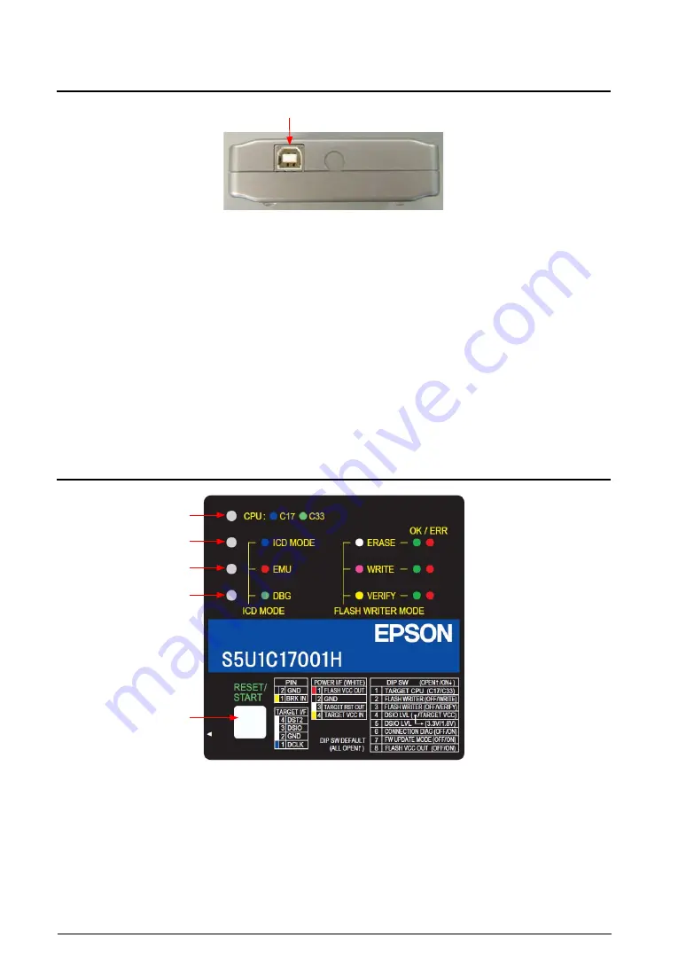
3.2 Right Side Panel
USB connector
Right Side Panel
USB connector
This connector is used to connect to a PC using the supplied USB cable.
Note
: When a bus-powered USB hub is used to connect the S5U1C17001H to the PC, there may be
a shortage of drive power. Especially if supplying the flash programming voltage, either connect
directly to the host computer’s USB port, or use an AC adapter (with USB 5 V output) capable of
supplying power to the USB cable.
If using an AC adapter, set the S5U1C17001H mode to be used and confirm beforehand that
erasing and writing is possible as desired.
3.3 Top Panel
Top Panel
LED1–LED4
The four LEDs located on the top panel indicate debugging and Flash programming statuses.
The indicated status differs between ICD mode and Flash programmer mode.
LED1
LED2
LED3
LED4
RESET/START switch


