
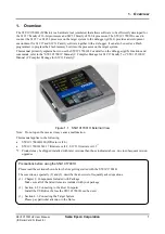

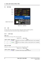
3. Name and Function of Each Part
6
Seiko Epson Corporation
S5U1C17001H2 User Manual
(ICDmini Ver2.0)
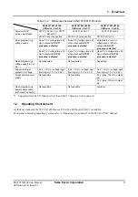
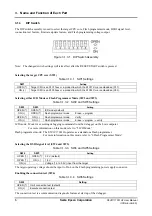
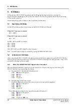
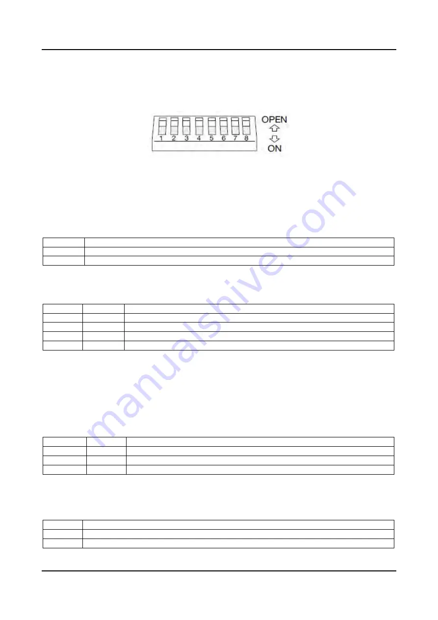
3.1.3 DIP
Switch
The DIP switch assembly is used to select the target CPU core, Flash programmer mode, DSIO signal level,
connection test feature, firmware update feature, and Flash programming voltage output.
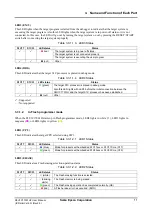
Figure 3.1.3.1 DIP Switch Assembly
Note: The changed switch settings will take effect after the RESET/START switch is pressed.
Selecting the target CPU core (SW1)
Table 3.1.3.1 SW1 Settings
SW1
Setting
OPEN (
)
Target CPU is an S1C17xxx or a product in which the S1C17 Core is embedded (C17).
ON (
)
Target CPU is an S1C33xxx or a product in which the S1C33 Core is embedded (C33).
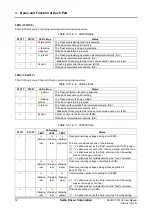
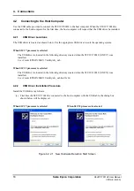
Selecting either ICD Mode or Flash Programmer Mode (SW2 and SW3)
Table 3.1.3.2 SW2 and SW3 Settings
SW2 SW3
Setting
OPEN (
) OPEN
(
)
ICD mode (default)
ON (
) OPEN
(
)
Flash programmer mode Erase
program
OPEN (
) ON
(
)
Flash programmer mode Verify
ON (
) ON
(
)
Flash programmer mode Erase
program
verify
ICD mode: Mode for executing debugging commands from the debugger on the host computer
For more information on this mode, refer to “5 ICD Mode.”
Flash programmer mode: The S5U1C17001H operates as a standalone Flash programmer.
For more information on this mode, refer to “6 Flash Programmer Mode.”
Selecting the DSIO signal level (SW4 and SW5)
Table 3.1.3.3 SW4 and SW5 Settings
SW4 SW5
Setting
OPEN (
) OPEN
(
)
3.3 V (default)
OPEN (
) ON
(
) 1.8
V
ON (
)
–
Voltage (1.0 to 5.5 V) input from the target
The target operating voltage should be input to Pin 4 on the Flash programming power supply connector.
Enabling the connection test (SW6)
Table 3.1.3.4 SW6 Settings
SW6 Setting
OPEN (
)
Omit connection test (default)
ON (
)
Execute connection test
The connection test is a communication diagnostic feature at start up of the debugger.


