3. Name and Function of Each Part
S5U1C17001H2 User Manual
Seiko Epson Corporation
7
(ICDmini Ver2.0) (Rev2.0)
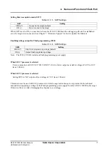
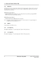
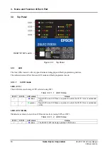
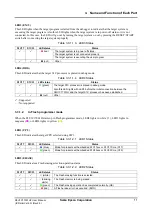
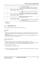
Setting firmware update mode (SW7)
Table 3.1.3.5 SW7 Settings
SW7 Setting
OPEN (
)
Connect to the target (default)
ON (
)
Do not connect to the target
When SW7 is set to ON, a connection between the S5U1C17001H and the debugger (gdb) can be established
even if a target is not connected. See Chapter 7, “Firmware Update,” for how to update the firmware.
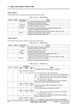
Enabling voltage output for Flash programming (SW8)
Table 3.1.3.6 SW8 Settings
SW8 Setting
OPEN (
)
Stop Flash programming voltage (default)
ON (
)
Output Flash programming voltage
Note: The S5U1C17001H includes a Flash programming power supply.
When S1C17 processor is selected
Use in conjunction with S5U1C17001C (GNU17 v2.0.0 or later) outputs a variable voltage of 6.0 V to 8.0 V
(max. 100 mA).
When S1C33 processor is selected
Setting SW8 to “On” outputs a fixed voltage of 7.0 V (max. 100 mA).
This must never be used with S1C processors for which usage instructions are not provided in the technical
manual when supplying a voltage as the Flash programming power supply from the S5U1C17001H to the target.
Otherwise, there is a risk of damaging the chip due to overvoltage.


