5. ICD
Mode
S5U1C17001H2 User Manual
Seiko Epson Corporation
21
(ICDmini Ver2.0) (Rev2.0)
5.2.2
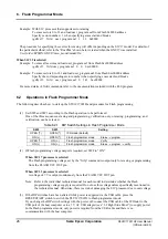
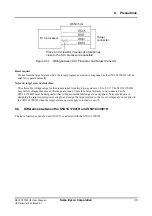
When the TARGET RST OUT Signal is Connected
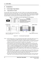
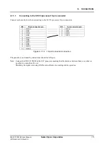
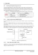
When the TARGET RST OUT signal is connected to the reset input on the target system, just press the RESET/
START switch on the S5U1C17001H for starting up. The S5U1C17001H automatically generates a target reset
signal with the proper connection sequence.
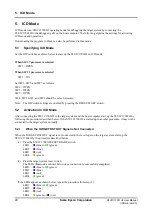
(1) Press the RESET/START switch on the S5U1C17001H.
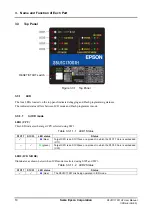
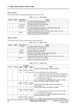
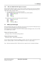
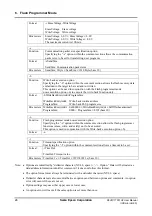
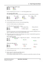
The LEDs illuminate as shown below once connection is successfully completed.
LED1
(blue) or
(green)
LED2
(blue)
LED3
(out)
LED4
(green)
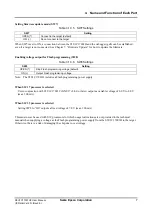
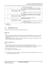
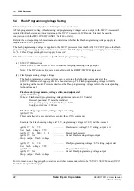
If the LEDs appear as shown below, repeat the procedure from step (1).
LED1
(blue) or
(green)
LED2
(blue)
LED3
(red)
LED4
(green) or
(out)
5.3
Starting Up the Debugger
Start up the debugger (gdb) on the host computer after the connection between the S5U1C17001H and the target
S1C processor has been established by the operations described above.
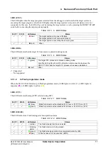
When debugging using the debugger with the S5U1C17001H connected, the debugger must be set to each mode
by executing the target command.
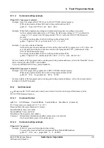
When the S1C17 processor is selected
(gdb) target icd usb
ICD mini mode setting command
When the S1C33 processor is selected
(gdb) target icd6 usb
ICD6 mode setting command
For more details of debugger commands and debugger operations, refer to the “S5U1C17001C Manual (S1C17
Family C compiler package)” or “S5U1C33001C Manual (S1C33 Family C compiler package).”
Note: Before disconnecting the S5U1C17001H from the host computer, be sure to terminate the debugger.

