
6. Flash
Programmer
Mode
S5U1C17001H2 User Manual
Seiko Epson Corporation
27
(ICDmini Ver2.0) (Rev2.0)
Waiting for connection with the target
ERASE
(out)
WRITE
(red)
VERIFY
(green)
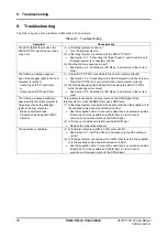
For more information on errors, refer to “3.3.1.2 In Flash programmer mode.”
After connecting with the target
The LEDs illuminate as shown below for the selected operations once it has started up successfully.
Erase
Write
Verify
Erase
Write
Verify
ERASE
(white)
(out)
(white)
WRITE
(magenta)
(out)
(magenta)
VERIFY
(out)
(yellow)
(yellow)
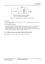
(4) Connect the target system to the S5U1C17001H.
(5) Press the RESET/START switch to start user program programming.
The S5U1C17001H starts the selected Flash operation.
The LED indicates the operation being executed.
During erasing
During programming
During verification
ERASE
(blinking white)
–
–
WRITE –
(blinking magenta)
–
VERIFY –
–
(blinking yellow)
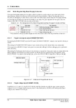
When the S1C17 processor is selected, the Flash programmer can also be started by inputting a low level
signal to the BRK IN pin instead of using the RESET/START switch.
(6) When the Flash operation has finished, the LED lights as shown below to indicate that the operation has
completed normally or an error has occurred.
When completed normally
Erasing has completed
Programming has completed
Verification has completed
ERASE
(green)
–
–
WRITE –
(green) –
VERIFY –
–
(green)
When an error has occurred
Erase error
Program error
Verify error
ERASE
(red) –
–
WRITE –
(red) –
VERIFY –
–
(red)
For more information on errors, refer to “3.3.1.2 In Flash programmer mode.”
(7) Disconnect the target system.
(8) Return to Step (4) to continue the same Flash operation.
Return to Step (1) to change the Flash operation.
When finishing Flash programming, disconnect the USB cable and set the DIP switch back to ICD mode.


