1. Overview
2
Seiko Epson Corporation
S5U1C17001H2 User Manual
(ICDmini Ver2.0)
1.1 Features
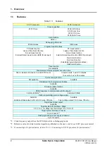
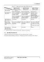
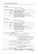
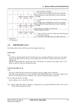
Table 1.1.1 Features
S1C17 processor
S1C33 processor
Cores supported
S1C17 Core
S1C33 STD Core
S1C33 mini Core
S1C33 PE Core
S1C33 ADV Core
Host interface
USB 1.1
Debugger (gdb) mode
ICD Mini mode
ICD6 mode
Program break functions
PC break function
Lapse of time break function
Forced break function
External forced break function (BRK IN pin input)
PC break function
Lapse of time break function
Forced break function
External forced break function (BRK IN pin input)
Area break function
Bus break function
(Selectable logical/physical address)
Data break function
Trace function
Not available
Measurement of target program execution time
Can be measured between 3
s and 6515 hours
In second units: 3 µs to 36 minutes
In
s units: 3
s to 1.8 minutes
Cycle counting function
Not available
Available
Standalone Flash programmer function
Available
Firmware update function
Available
DCLK frequency to communicate with the target
*1
4 kHz to 40 MHz
*2
4 kHz to 40 MHz
Flash programming power voltage supply
Available
Variable voltage output: 6.0 V to 8.0 V (max. 100 mA)
Available
Fixed voltage output: 7.0 V (max. 100 mA)
Target reset signal output
Available
Target system I/O interface voltage
3.3 V, 1.8 V, or voltage input from target (1.0 V to 5.5 V)
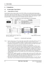
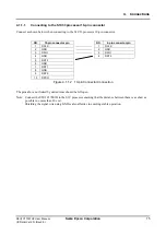
Target system interface connector
4-pin connector
*3
Flash programming power supply connector
4-pin connector
*1: Clock frequency output from the DCLK pin while in Debugging mode.
*2: Reference values for data download speed are published on the user’s site for each S1C processor model.
*3: If connecting a 10-pin connector, refer to “4.1.1.1 Connecting to S1C33 processor 10-pin connector.”

