
1. Overview
S5U1C17001H2 User Manual
Seiko Epson Corporation
3
(ICDmini Ver2.0) (Rev2.0)
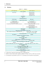
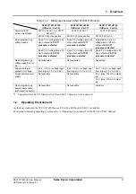
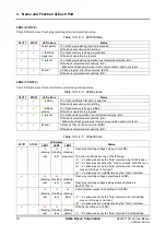
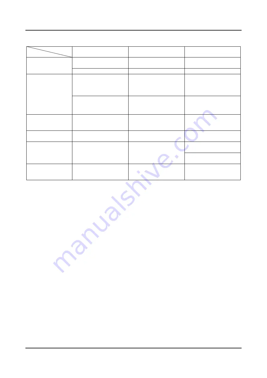
Table 1.1.2 Differences between S5U1C17001H Products
S5U1C17001H1100
(ICDmini Ver1.0)
S5U1C17001H1200
(ICDmini Ver1.1)
S5U1C17001H2100
(ICDmini Ver2.0)
S1C17 FW Ver1.0 or S1C17
FW Ver1.1
S1C17 FW Ver1.1
S1C17 FW Ver3.2
Firmware (FW)
version as shipped
S1C33 FW not supported
S1C33 FW not supported
S1C33 FW Ver1.5
Fixed 7.0 V voltage (max. 30
mA) output with
S1C17
processor selected
Fixed 7.0 V voltage (max. 30
mA) output with
S1C17
processor selected
Variable 6.0 V to 8.0 V
voltage (max. 100 mA)
output with
S1C17
processor selected
*1
Flash programming
voltage supply
Fixed 7.0 V voltage (max. 30
mA) output with
S1C33
processor selected
Fixed 7.0 V voltage (max. 30
mA) output with
S1C33
processor selected
Fixed 7.0 V voltage (max. 30
mA) output with
S1C33
processor selected
*1
Flash programming
voltage supply to V
pp
pin
Not supported
Not supported
Supported
Supported target
system I/O voltage
3.3 V, 1.8 V, or voltage input
from target (1.0 V to 5.0 V)
3.3 V, 1.8 V, or voltage input
from target (1.0 V to 5.5 V)
3.3 V, 1.8 V, or voltage input
from target (1.0 V to 5.5 V)
3.3 V (max. 100 mA) output
pin
Target system power
supply
Not available
Not available
1.8 V (max. 100 mA) output
pin
Flash programming
power supply cable
(with black connector)
Not available
Not available
Available
*1: Supported from S1C17 firmware Ver3.0 and S1C33 firmware Ver1.4 onward.
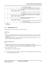
1.2 Operating
Environment
As the host computer, the S5U1C17001H uses a PC with a USB port (USB 1.1) available.
For details concerning operating systems, refer to “Operating Environment” in the S5U1C17001C Manual.


