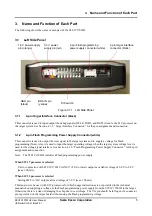
3. Name and Function of Each Part
8
Seiko Epson Corporation
S5U1C17001H2 User Manual
(ICDmini Ver2.0)
3.1.4
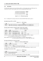
BRK IN Pin
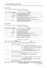
In ICD mode, if a Low level signal is input to this pin when the target program is being executed, execution of
the target program is suspended. After a Low level is input to the BRK IN pin, a break will occur after a few
instructions have been executed.
With S1C17 processor selected
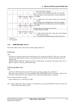
In Flash programmer mode, inputting a Low level to this pin has the same effect as pressing the RESET/
START switch (it starts erasing/writing/verification).
With S1C33 processor selected
In Flash programming mode: BRK IN pin does not function.
Note: The voltage to apply to the BRK IN pin must be 0 V for low level and 3.3 V or open for high level.
The BRK IN pin is always pulled up to 3.3 V.
3.1.5 GND
Pin
Connect this pin to the GND level (0 V).
3.1.6
3.3 V Output Pin
Pin capable of supplying a 3.3 V power supply (max. 100 mA) to the target system.
3.1.7
1.8 V Output Pin
Pin capable of supplying a 1.8 V power supply (max. 100 mA) to the target system.


