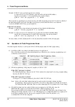
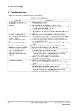

7. Firmware
Update
28
Seiko Epson Corporation
S5U1C17001H2 User Manual
(ICDmini Ver2.0)
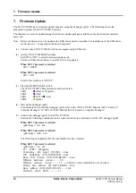
7. Firmware
Update
The S5U1C17001H has a firmware update function using the debugger (gdb). T he following shows the
procedure to update the S5U1C17001H firmware.
The firmware can also be updated using the firmware update package available on the Epson microcontroller
users’ site.
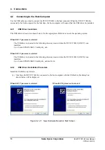
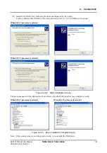
Note: Before the firmware can be updated, the USB driver must be installed. For installation of the USB driver,
see Section 4.2, “Connecting to the Host Computer.”
(1) Connect only S5U1C17001H to the host computer using USB cable.
(2) Set the S5U1C17001H DIP switches.
Set SW7 to “ON” to select Firmware update mode.
Set the switches shown below to suit the S1C to be updated.
When S1C17 processor is selected
SW1 = OPEN
When S1C33 processor is selected
SW1 = ON
Set all other switches to “OPEN.”
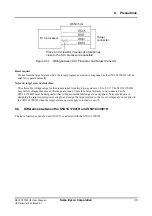
(3) Press the RESET/START switch.
The S5U1C17001H LEDs illuminate as shown below.
LED1
(blue) or
(green)
LED2
(blue)
LED3
(red) or
(out)
LED4
(green)
(4) Start up the debugger (gdb).
For details of how to start the debugger (gdb), refer to the “S5U1C17001C Manual (S1C17 Family C
Compiler Package)” or “S5U1C33001C Manual (S1C33 Family C Compiler Package).”
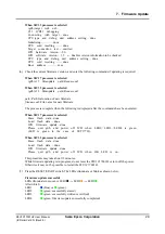
(5) Connect the debugger (gdb) to the S5U1C17001H.
Execute the following commands via the console window in accordance with the S1C debugger (gdb).
When S1C17 processor is selected
(gdb) target icd usb
When S1C33 processor is selected
(gdb) target icd6 usb
The following is displayed after the commands have been entered.
When S1C17 processor is selected
(gdb) target icd usb
C17 ICD17 debugging
Connecting with target (ID_OK) ..... done
ICD Initializing (ICD_INITALIZE) ... done
Read ICD Version (ICD_VER_READ) ..... done
ICDmini hardware version .......... 2.0
ICDmini software version .......... 3.2
Enables version information to be checked
Debug base address (ID_DATA_READ) .. xxxx
Boot address (ICD_DATA_READ) ........ xxxx
Hardware break MAX ................xx


