S5U1C17564T Manual
Seiko Epson Corporation
i
(Rev.1.0)
Table of Contents
1.
Overview ..................................................................................................................... 1
1.1
Using the board ....................................................................................................................... 2
2.
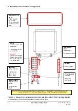
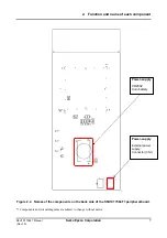
Function and name of each component .................................................................. 4
2.1
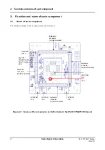
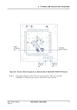
Name of each component ....................................................................................................... 4
2.2
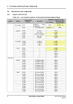
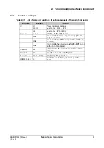
Function of each component.................................................................................................. 8
2.2.1
Jumper switch function........................................................................................................ 8
2.2.2
Function of each part .......................................................................................................... 9
3.
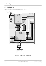
Block diagram .......................................................................................................... 10
4.
Connector ..................................................................................................................11
4.1
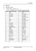
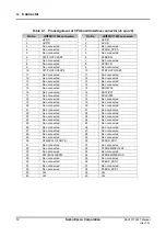
CPU board connector ............................................................................................................ 11
4.1.1
CPU board interface connector (J1 - J4)........................................................................... 11
4.1.2
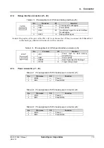
Debug interface connector (J5 - J6) .................................................................................. 13
4.1.3
Power connector (J7 - J9) ................................................................................................. 13
4.2
Peripheral board connector .................................................................................................. 14
4.2.1
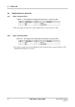
Power connector (CN1)..................................................................................................... 14
4.2.2
Power connector (CN3)..................................................................................................... 14
4.2.3
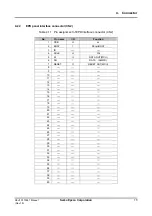
EPD panel interface connector (CN2) ............................................................................... 15
Appendix A
File organization of the sample software .............................................. 16
Appendix B
Circuit diagrams and parts list............................................................... 17
Revision History ............................................................................................................. 20

