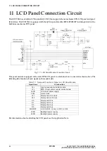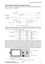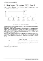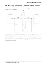
8
JUMPER SWITCH SETTINGS
24
EPSON
S5U1C17801T1100 HARDWARE MANUAL
(SOFTWARE EVALUATION TOOL FOR S1C17801)
Setting for JP
3
JP
3
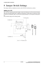
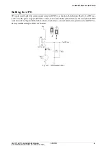
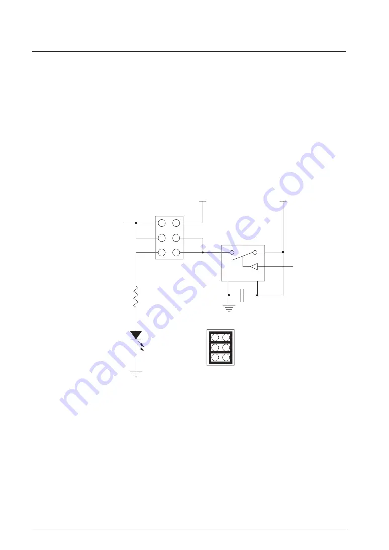
wiring, allowing for three functions, is shown in the following.
∗
1
-
2
Shorted
Power is supplied to LCD backlight. Shorting
3
-
4
is not allowed while
1
-
2
is shorted.
∗
3
-
4
Shorted
Power with phase generated by.MFT
0
on the S
1
C
17801
is supplied to LCD backlight. It can be used to adjust the
brightness of LCD backlight. Shorting
1
-
2
is not allowed while
2
-
3
is shorted. For details, see Chapter
15
“
LED/
LCD BACKLIGHT CONTROL CIRCUIT WITH MFT
0
.
”
∗
5
-
6
Shorted
Power with phase generated by MFT
0
is supplied to LED
3
. It can be used to adjust the brightness of LED
3
. Ei-
ther
1
-
2
or
2
-
3
can be shorted while
5
-
6
is shorted. For details, see Chapter
15
“
LED/LCD BACKLIGHT CON-
TROL CIRCUIT WITH MFT
0
.
”
Factory default setting for JP
3
is
1
-
2
and
5
-
6
shorted.
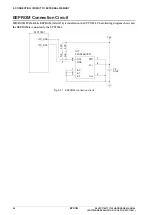
DIC-152-6P
1
1
5
3
5
3
2
6
4
2
4
G
V
V
DD
VLSS (LCD module)
V
DD
JP3
JP3
MFT0
U20
TS5A3166
R90
470
LED3
LTW-170TK
C65
0.1µF
LCD_BL_ON
LCD_BL_PWM
D201_PWM
Fig.
8
.
3
.
1
JP
3
Related Circuit
Summary of Contents for S5U1C17801T1100
Page 4: ......

