13
ROTARY ENCODER CONNECTION CIRCUIT
S5U1C17801T1100 HARDWARE MANUAL
EPSON
35
(SOFTWARE EVALUATION TOOL FOR S1C17801)
13
Rotary Encoder Connection Circuit
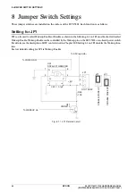
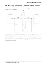
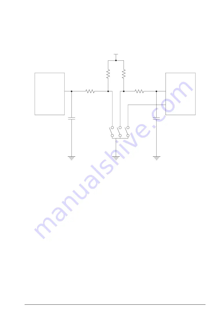
The rotary encoder connected to the SVT
17801
is connected with three port inputs (P
31
, PC
0
and PC
1
) on the
S
1
C
17801
as shown in the figure
13
.
1
.
0.01µF
0.01µF
A
COM
B
S
10K
S1C17801
PC0
PC1
P31
S1C17801
10K
10K
10K
V
DD
Fig.
13
.
1
Rotary Encoder Connection Circuit
Rotating the rotary encoder closes the A and B switches shown above, and the time difference of switching occurs
depending on the rotative direction. When the encoder does not rotate, both of two ports connected to the S
1
C
17801
are pulled up to HIGH. When the encoder rotates, on the contrary, they are turned LOW, and phase difference arises
between the HIGH and LOW timings of those ports. The phase difference can be detected by software to govern
the rotative direction. As a switch is directly connected to a port, pressing the switch turns the port LOW. The LOW
zone can be detected by software.
Summary of Contents for S5U1C17801T1100
Page 4: ......


