16
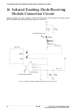
INFRARED EMITTING DIODE/RECEIVING MODULE CONNECTION CIRCUIT
S5U1C17801T1100 HARDWARE MANUAL
EPSON
39
(SOFTWARE EVALUATION TOOL FOR S1C17801)
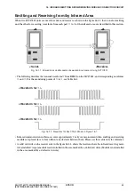
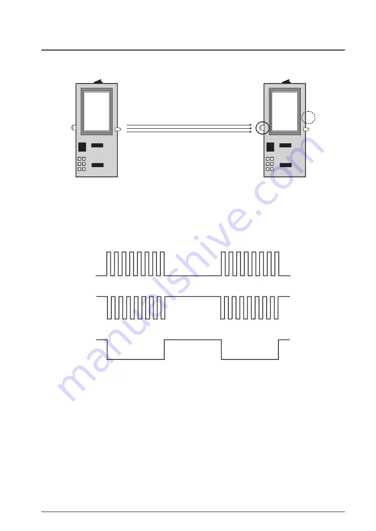
Emitting and Receiving from/by Infrared Area
When two SVT
17801
units are used for sender and receiver as shown in the figure
16
.
1
.
1
, that is one for emitting
and the other for receiving, waveform from each part
➀
to
➂
of the infrared area are described in this section.
<Send>
<Receive>
Fig.
16
.
1
.
1
Infrared Emission/Reception Evaluation Environment Using SVT
17801
∗
The following describes the transmit waveform
➀
from REMO on the S
1
C
17801
, and corresponding waveforms
➁
and
➂
. For the monitoring points of
➀
to
➂
, see Table
16
.
1
.
<Waveform for
➀
>
<Waveform for
➁
>
<Waveform for
➂
>
Fig.
16
.
1
.
2
Waveform for Each Point Shown in Figure
16
.
1
∗
Infrared communication in this case covers approximately
3
m by our measurement when emitting and receiving
modules are placed face to face without any obstacle between them. Please use this value only for reference.
∗
A solid red circle on the receiver side in the figure
16
.
1
.
1
. shows the location where the infrared receiving mod-
ule is installed. A spare module can be installed in the area marked by a dotted red circle. (Module is not installed
in the area marked by a dotted red circle.)
Summary of Contents for S5U1C17801T1100
Page 4: ......

