SC-F2000
Revision C
ADJUSTMENT
TF Adjustments
270
Confidential
[Blue]:
Button or menu name on the program screen /
[Black]:
Button or menu name on the operation panel of the printer
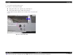
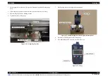
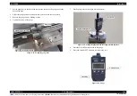
10. Remove the gauge unit from the origin position adjuster.
11. Remove the PLATEN from the TABLE ASSY.
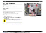
12. Set the height of the PLATEN to “P” and secure it with the Fixing Lever.
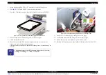
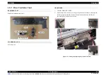
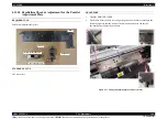
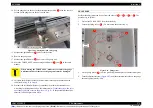
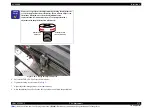
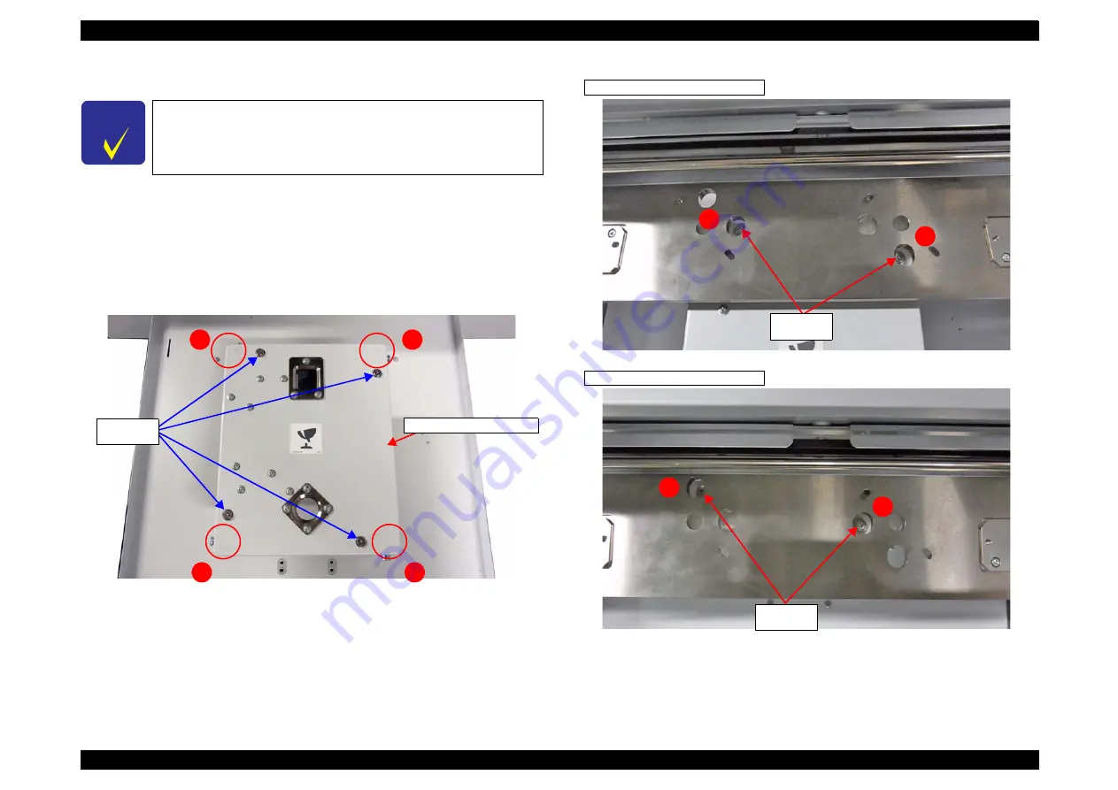
13. Manually move the Parallel Adjustment Plate slowly to the measurement point.
The measurement point is the point from where the adjustment screws can be seen
from the holes on the base. The measurement positions and the measuring order
are as follows.
Figure 4-81. The measurement positions and order for the Parallel Adjustment Plate
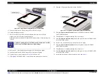
Figure 4-82. Checking the measurement positions
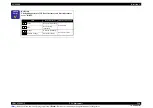
C H E C K
P O I N T
The value on the gauge changes after the gauge is removed from the
adjuster, the value should be changed from “0” is not a problem
and does not affect the result.
1
2
3
4
Parallel Adjustment Plate
Adjustment
screws
1
2
4
3
Adjustment
screws
Adjustment
screws
Measurement positions of (1) and (2)
Measurement positions of (3) and (4)
Summary of Contents for SC-F2000 Series
Page 1: ...SC F2000 Direct To Garment Printer SERVICE MANUAL SECP13002 Confidential ...
Page 10: ...Confidential C H A P T E R 1 PRODUCTDESCRIPTION ...
Page 29: ...Confidential C H A P T E R 2 TROUBLESHOOTING ...
Page 52: ...Confidential C H A P T E R 3 DISASSEMBLY ASSEMBLY ...
Page 192: ...Confidential C H A P T E R 4 ADJUSTMENT ...
Page 285: ...Confidential C H A P T E R 5 MAINTENANCE ...

