GRAPHICS
SED1352
X16B-C-001-06
14
■
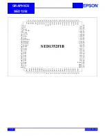
PIN DESCRIPTION
Key
Bus Interface
A
= Analog
I
= Input
O
= Output
I/O = Bidirectional
P
= Power
Pin Name Type F0B Pin #
F1B Pin #
D0B Pad
#
Description
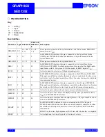
DB0-DB15 I/O
94 - 100, 1,
4 -11
91 - 98,
1 - 8
These pins are connected to the system data bus. In 8-bit bus mode, DB8-DB15
must be tied to V
DD
.
AB0
I
12
9
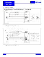
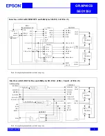
In MC68000 MPU interface, this pin is connected to the Upper Data Strobe
(UDS#) pin of MC68000. In other bus interfaces, this pin is connected to the
system address bus.
AB1-AB19 I
13 - 31
10 - 28
These pins are connected to the system address bus.
BHE#
I
91
88
In MC68000 MPU interface, this pin is connected to the Lower Data Strobe
(LDS#) pin of MC68000. In other bus interfaces, this pin is the Bus High Enable
input for use with 16-bit system. In 8-bit bus mode, tie BHE# input to V
DD
.
IOCS#
I
84
81
Active low input to select one of fifteen internal registers.
IOW#
I
85
82
In MC68000 MPU interface, this pin is connected to the R/W# pin of MC68000.
This input pin will define whether the data transfer is a read (active high) or write
(active low) cycle. In other bus interfaces, this is the active low input to write data
into an internal register.
IOR#
I
86
83
In MC68000 MPU interface, this pin is connected to the AS# pin of MC68000.
This input pin will indicate a valid address is available on the address bus. In other
bus interfaces, this is the active low input to read data from an internal register.
MEMCS#
I
87
84
Active low input to indicate the attempt to access the display memory.
MEMW#
I
88
85
Active low input to write data to the display memory. This pin should be tied to
V
DD
in an MC68000 MPU interface.
MEMR#
I
89
86
Active low input to read data from the display memory. This pin should be tied to
V
DD
in an MC68000 MPU interface.
READY
O
90
87
For MC68000 MPU interface, this pin is connected to the DTACK# pin of
MC68000 and will be driven low when ever a data transfer is complete. In other
bus interfaces, this output is driven low to force the system to insert wait states
when needed.
READY is placed in a high-impedance (Hi-Z) state after the transfer is completed.
RESET
I
32
29
Active high input to force all signals to their inactive states.


