Function 11. Stand-alone Option for SRC520
92
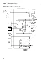
Example 2: External safety relay typical application
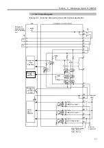
Latch Release input
Close: latch off
Open: latch on
Emergency
Stop switches
of an operating
unit
Emergency
Stop
detection
Safety
Door
detection
Safety Door input1
Safety Door input 2
Latch Release input
Ex24VGND
Emergency Connector Board
E24V
Fuse*
External
+24VGND
External safety relay
(The above diagram
is simplified for
representation.)
For the protection
of the emergency stop
circuit, the fuse’s
capacity should be as
follows:
•
Meet the capacity
of the external
safety relay
•
1A or less
Ex24V
Ex24VGND
Emergency
Stop
condition
control
Emergency
Stop
detection
External
+24V
Summary of Contents for SRC520
Page 1: ...SRC520 Rev 4 EM015C868F ROBOT CONTROLLER ...
Page 2: ...ROBOT CONTROLLER SRC520 Rev 4 ...
Page 13: ...Function The manual herein explains in detail the functions of the robot controller SRC520 ...
Page 14: ...Function 2 ...
Page 29: ...Function 2 3 Control Unit Part Names and Functions 17 2 3 4 Dimensions mm ...
Page 35: ...Function 2 4 Drive Unit Part Names and Functions 23 2 4 5 Dimensions mm ...
Page 36: ...Function 2 4 Drive Unit Part Names and Functions 24 ...
Page 50: ...Function 3 5 Noise Countermeasures Installation 38 ...
Page 66: ...Function 6 3 Pin Assignments D I O Connector 54 ...
Page 96: ...Function 9 2 Preparation for Communication RS 232C Settings 84 ...
Page 106: ...Function 11 Stand alone Option for SRC520 94 ...
Page 108: ...Maintenance 96 ...
Page 139: ...Maintenance 4 3 Drive Unit Drive Unit 127 4 3 Drive Unit 4 3 1 System Configuration ...

