Maintenance 2. Hardware Configuration
100
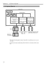
2.2 Optional Boards
*
One Pulse Generating Board increases the
number of controllable axes by four (4) at
maximum.
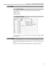
For details about jumper and data settings of the boards, refer to the manual attached to each
board.
Control Unit
Input/output Equipment Total
(input/output included): 128
Input/output Equipment
Input :32
Output :32
Drivers
Computer
MIB
MIB
MIB
Optional Boards
.......
.......
Pulse Generating
Board*
(Set the jumper for
I/O address)
Extension I/O Board
(Set the jumper for
I/O address)
Remote I/O Board
(Set the jumper for
I/O address and
the number of I/O)
Motors of
manipulator (s)
Summary of Contents for SRC520
Page 1: ...SRC520 Rev 4 EM015C868F ROBOT CONTROLLER ...
Page 2: ...ROBOT CONTROLLER SRC520 Rev 4 ...
Page 13: ...Function The manual herein explains in detail the functions of the robot controller SRC520 ...
Page 14: ...Function 2 ...
Page 29: ...Function 2 3 Control Unit Part Names and Functions 17 2 3 4 Dimensions mm ...
Page 35: ...Function 2 4 Drive Unit Part Names and Functions 23 2 4 5 Dimensions mm ...
Page 36: ...Function 2 4 Drive Unit Part Names and Functions 24 ...
Page 50: ...Function 3 5 Noise Countermeasures Installation 38 ...
Page 66: ...Function 6 3 Pin Assignments D I O Connector 54 ...
Page 96: ...Function 9 2 Preparation for Communication RS 232C Settings 84 ...
Page 106: ...Function 11 Stand alone Option for SRC520 94 ...
Page 108: ...Maintenance 96 ...
Page 139: ...Maintenance 4 3 Drive Unit Drive Unit 127 4 3 Drive Unit 4 3 1 System Configuration ...


