background image

Maintenance        3.2 Replacing the MIB (Control Unit) 


104 

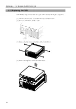
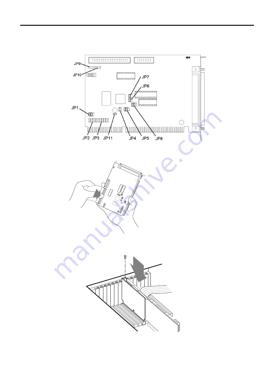
(8)  Set the jumpers on the new MIB exactly the same as on the old board. 

Refer to the “Function 10. Jumper Settings for MIB (Motion Interface Board)” for 
details of the jumper functions. 


(9)  Connect the cable from the System panel to the new MIB. 


(10) Mount the new MIB onto the option slot in the Control Unit and fasten the screw to 

secure the new board. 


Summary of Contents for SRC520

Page 1: ...SRC520 Rev 4 EM015C868F ROBOT CONTROLLER ...

Page 2: ...ROBOT CONTROLLER SRC520 Rev 4 ...

Page 3: ...i ROBOT CONTROLLER SRC520 Rev 4 Copyright 1998 2000 2001 SEIKO EPSON CORPORATION All rights reserved ...

Page 4: ... s malfunctions resulting from normal handling and operation will be repaired free of charge within this warranty period Any other repairs after this warranty period ought to be in voiced 3 Escape Clause Customers will be charged for repairs in the following cases even if it is within the warranty period 1 Damage or malfunction caused by improper use which is not described in the manual or careles...

Page 5: ...ts regarding its content TRADEMARKS Pentium is a trademark of the Intel Corporation Microsoft is a registered trademark and Windows and Windows logo are registered trademarks of the Microsoft Corporation Other brand and product names are trademarks or registered trademarks of the respective holders Please direct any inquiries about the use of this manual to SRC520 SEIKO EPSON CORPORATION Sales Eng...

Page 6: ...read the Introduction Man ual first to follow Safety Precautions therein This robot has been designed and manufactured strictly for use in a normal indoor environment Do not use the robot in an environment that exceeds the conditions set forth in the manuals for the manipulator and controller Do not use the robot outside of the usage conditions and product specifica tions described in the manuals ...

Page 7: ...ler options z Multi Manipulator Manual z Pulse Generating Board Manual z Ethernet Board Manual z Remote I O Board Manual z Vision Calibration Guide z M300 Micro Image checker z Custom Manipulator Tuning z Operation Pendant OP500 Manual Revised Points from SRC500 SRC520 is a succeeding model to SRC500 The function operation and external dimension have not been changed The main revised points are as...

Page 8: ... and SRC520CE Control Unit with SPEL 95 compose a SRC520CE SRC520CE will not meet the above mentioned Standards when the SRC520CE is remodeled and or when the SRC520CE is connected with other controller SRC520CE provides only PNP type I O SRC520 provides NPN type I O but PNP type is prepared as an option SERVICE CENTER Contact the following service center for robot repairs inspections or adjustmen...

Page 9: ...s 23 3 Installation 25 3 1 Box Contents 25 3 2 Environmental Requirements 26 3 3 Power Supply 27 3 3 1 Specifications 27 3 3 2 Power Plug 28 3 4 Cable Connection 29 3 4 1 Typical Cable Connection Single Manipulator 30 3 4 2 Connecting Drive Unit and Control Unit 33 3 4 3 Connecting a Drive Unit to the Manipulator 35 3 5 Noise Countermeasures 36 4 OPTIONAL DEVICE Connector 39 4 1 OPTIOINAL DEVICE C...

Page 10: ... Circuit 59 7 3 Extension I O Board the standard for the regions outside Europe 61 7 3 1 Jumper Settings 61 7 3 2 Input Circuit 62 7 3 3 Output Circuit 62 7 4 Extension I O Board Pin Assignments 64 7 4 1 Pin Assignments NPN type 64 7 4 2 Pin Assignments PNP type 66 7 5 Extension I O Connector 68 7 5 1 Pin Layout of Extension I O Connector 68 7 5 2 Extension I O Connector Cable 68 7 5 3 Cable Pin A...

Page 11: ...gnments 90 11 5 5 Circuit Diagram 91 11 6 MIB 93 11 6 1 Board Number 93 11 6 2 Jumper Settings 93 11 7 Option 93 Maintenance 1 Safety Precautions on Maintenance 97 2 Hardware Configuration 99 2 1 Control Unit Drive Unit and Manipulator 99 2 2 Optional Boards 100 3 Control Unit 101 3 1 Overview 101 3 2 Replacing the MIB 102 3 3 Replacing the Extension Emergency Connector Unit 106 3 4 Replacing an O...

Page 12: ...le 131 4 4 3 Setting Up the New CT Data on the SPEL 95 133 4 5 DPB Drive Power Board 134 4 5 1 Layout and Functions 134 4 5 2 Adjusting Encoder Voltage 136 4 5 3 Adjusting 5V Voltage 137 4 6 DMB Drive Main Board 138 4 6 1 Layout and Functions 138 4 6 2 Replacing DMB 139 4 7 Cooling Fan 142 4 7 1 Layout 142 4 7 2 Inspecting the Fan Filter 142 4 7 3 Replacing the Fan 143 4 8 Regeneration Module 145 ...

Page 13: ...Function The manual herein explains in detail the functions of the robot controller SRC520 ...

Page 14: ...Function 2 ...

Page 15: ...AC power cable colored green yellow to the earth terminal of the factory power supply The equipment must be grounded properly at all times to avoid the risk of electric shock Always use a power plug Never connect the controller directly to the factory power supply Make sure that the power to the Control Unit and Drive Unit is turned OFF before connecting or disconnecting any cables Failure to do s...

Page 16: ...cted to the Control Unit make sure that the DU numbers DU1 DU3 indicated at the Control Unit above the MIB connector and the Drive Unit above the MOTION connector match It is highly dangerous if those do not match causing to activate an unintended robot Ensure all cables are securely connected Avoid placing anything heavy on the cables and do not bend them excessively because this may damage the c...

Page 17: ... the switch is pressed the motor power is shut down right away and the robot will enter the emergency stop condition Safety Door Input Opening the Safety Door stops the robot right away for the time being In order to activate this feature make sure that the Safety Door Input switch is connected to the EMERGENCY connector at the Drive Unit Low Power Mode The motor power is reduced in this mode Duri...

Page 18: ...l position is detected to mark an overflow the actual position is outside the nominal range error Speed Overflow Servo Error Detection The dynamic brake circuit is activated when the robot s actual speed is detected to mark an overflow the actual speed is outside the nominal range error CPU Irregularity Detection Irregularity at the motor controlling CPU is detected by the watch dog timer Also the...

Page 19: ...e Unit s One Drive Unit enables controlling up to 4 axes motors at once Up to three Drive Units can be connected to one Control Unit For details of the Control Unit refer to the Function 2 3 Control Unit For details of the Drive Unit refer to the Function 2 4 Drive Unit Example 1 One Drive Unit and One Manipulator Control Unit Drive Unit Manipulator Jog Pad option ...

Page 20: ...stem Configuration Part Names and Functions 8 Example 2 Three Drive Units and Three Manipulators Control Unit Jog Pad option 3rd Manipulator 2nd Manipulator 1st Manipulator 1st Drive Unit 2nd Drive Unit 3rd Drive unit ...

Page 21: ... motion Programmable in the range of 1 to 100 CP motion programmable Actual value to be manually entered Robot Manipulator Control Acceleration Deceleration Control PTP motion Programmable in the range of 1 to 100 Automatic CP motion programmable Actual value to be manually entered Positioning Control PTP Pose To Pose control CP Continuous Path control Memory Capacity Programmable Area 2MB Pose Da...

Page 22: ...pecial optional cable is prepared Pulse Generating Board 4 additional controllable axes one board A special optional cable is prepared Remote I O Board Input and Output total 128 Ethernet Board Vision Option Multi Manipulator Option Custom Manipulator Option Conveyor Tracking Option Jog Pad JP500 Operation Pendant OP500 Power Source AC 200V to AC 240V Single phase 50 60Hz Power Consumption Max 200...

Page 23: ...ications Part Names and Functions 11 SRC520CE is in conformity with the following EC directives Conformed to Applied Standards Machinery directive EN775 EN60204 1 EMC directive EN55011 EN50082 2 Low Voltage directive EN60950 520CE ...

Page 24: ...l equivalent under the condition that the power supply voltage switch is set at 115 side AC100V to AC120V the equipment will be damaged seriously As for the power supply when only using the Control Unit refer to the 11 4 Power Supply in the Function 11 Stand alone Option for SRC520 Only install optional hardware specifically designed for the SRC520 in the Control Unit Do not install any other soft...

Page 25: ...l indicates the specification number for the customized robot and is attached only to the customized robot If your robot indicates this label it may require a specific maintenance procedure For such robot with this label make sure to contact your dealer before any maintenance procedures 4 Cooling Fan Filter A filter for a cooling fan It can be pulled out to the right by pulling the tab forward The...

Page 26: ... table in the Appendix B Manipulator Number Two digit manipulator numbers are displayed starting from 01 Joint Number Two digit numbers are display showing which joint of the Manipulator has an error The number starts from 01 When an error occurs that has no relation to a manipulator or joint the error number will appear but the manipulator number and joint number will both be displayed as 00 8 HD...

Page 27: ...tion and centralized control by connecting peripheral equipment and the host computer to the Control Unit For details refer to the Function 9 RS 232C Settings 3 CPU Board The board packages a Pentium CPU The standard package includes 32MB memory The jumpers on the type MSC1551 CPU board are originally set as shown in the table Normally the default settings do not need to be changed for regular usa...

Page 28: ...trol Unit 7 Power Supply Voltage Switch The power supply voltage switch on the Control Unit must be set and kept at 230 side AC200V to AC240V when using the Control Unit with other equipment When only using the Control Unit the setting is different Refer to the Function 11 Stand alone Option for SRC520 for the 11 4 Power Supply 8 AC OUT The AC OUT connector outputs the power to the monitor 9 Keybo...

Page 29: ...Function 2 3 Control Unit Part Names and Functions 17 2 3 4 Dimensions mm ...

Page 30: ...n the CP motion is not used of controllable motor axes from the Pulse Generating P G Board s 0 1 2 3 4 5 6 7 8 9 10 11 12 13 16 0 1 2 Number of Manipulators 3 This Manipulator means a manipulator with the SRC520 Drive Unit of 4 motor axis capabilities The above tables presume the Control Unit equipped with Pentium MMX 200MHz CPU and RAM 32MB The indicates possible combination of the number of moto...

Page 31: ... installed behind the front panel 4 LED The LED on the front panel indicates the status of the Drive Unit during operation as follows LED Description 1 The number 1 indicates that an unresettable error relating to motor control with in any of the robot axes occurs 2 The number 2 indicates that a resettable error relating to motor control with in any of the robot axes occurs ERROR Lights when the C...

Page 32: ... Connect the dedicated power cable attached to the Manipulator 4 PE Terminal External protective conductor terminal 5 AC Power cable Cable for the AC200V or the local equivalent power input 6 EMERGENCY connector The connector is used for input output from to Emergency Stop and Safety Door switches Refer to the Function 5 EMERGENCY Connector for details 7 D I O connector The connector is used for c...

Page 33: ...lectrical shock even when its main power is OFF The figure below shows the interior of a Drive Unit 2 3 4 1 5 7 8 6 1 DMB Drive Main Board The Drive Main Board receives a position reference from the Control Unit and thereby drives the motor 2 Regeneration module This module protects the circuit from the regenerated electricity when the Manipulator consumes high electric power during operation A re...

Page 34: ...ive Unit equipped with the Regeneration module that generates more heat an additional cooling fan is packaged 6 Filter A protective filter is installed in front of the fan to screen dust Check condition of the filter regularly and clean it as necessary A dirty filter can cause the temperature inside the controller to rise which might cause the robot to malfunction 7 DPB Drive Power Board The Drive...

Page 35: ...Function 2 4 Drive Unit Part Names and Functions 23 2 4 5 Dimensions mm ...

Page 36: ...Function 2 4 Drive Unit Part Names and Functions 24 ...

Page 37: ... 1 set FD This program has already been installed in a Controller Metal Fitting and Angles 1 set PS 2 Keyboard Adapter 1 piece Board affixing screws and accessories 1 set Drive Unit Item Quantity Note Drive Unit 1 unit EMERGENCY Connector 1 piece Square half pitch 20 pin D I O Connector 1 piece Square half pitch 50 pin Motion Interface Cable 1 piece Length 70 cm The manipulator Power cable and Sig...

Page 38: ...ks or vibrations Keep away from sources of electronic noise If the controller must be used in an environment that does not fulfill the conditions mentioned above take adequate countermeasure For example the controller may be covered with a box having a cooling mechanism The controller is not designed for clean room specification If it is to be installed in a clean room it needs to be covered with ...

Page 39: ... Current When power is turned ON approximately 50A 2msec When motor is ON approximately 150A 5msec Leakage Current 6mA TYP Ground Resistance Less than 100Ω If you are to connect an earth leakage circuit breaker in the AC power cable line for the Drive Unit make sure to use an inverter type that does not induce a leakage current of more than 10kHz If you install a circuit breaker please select one ...

Page 40: ...he equipment must be protective earth wire properly at all times to avoid the risk of electric shock Always use the power plug Never connect the controller directly to the factory power supply Plug Specification Terminal Description Color X terminal AC power Brown Y terminal Open Z terminal AC power Blue W terminal Protective earth wire Green Yellow The Drive Unit s AC power cable is specified as ...

Page 41: ...cting those units If those units are misconnected the robot may not function properly or may be damaged If there are more than one Drive Units connected to a Control Unit make sure that the DU numbers DU1 DU3 indicated at the Control Unit above the MIB connector and the Drive Unit above the MOTION connector match It is highly dangerous if those do not match causing to activate an unintended robot ...

Page 42: ...nipulator Control Unit MOTION Extension I O option MONITOR MOUSE KEYBOARD ACIN OPTIONAL DEVICE Drive Unit M C POWER M C SIGNAL MOTION D I O Standard EMERGENCY AC OUTLET INPUT PE 1 M C Power Cable 2 M C Signal Cable 3 Motion Interface Cable 4 D I O 5 EMERGENCY 6 PC Power Cable 7 AC Power Cable 8 PE Input output unit E STOP switch Safety Door switch AC200V power Protective earth Input output unit Mo...

Page 43: ...onnector A connector is to connect with the user s input output device If you have input output units connect them to this connector For details about D I O refer to the Function 6 D I O Connector 5 EMERGENCY connector The EMERGENCY connector has inputs to connect the emergency stop switch and the safeguard switch For safety reasons connect proper switches for these input devices For details refer...

Page 44: ... connector The PE terminal connects to the Protective earth wire The PE terminal is better to be connected when several robots are used in a line or when a peripheral control unit such as a sequencer is used in the system Use a cable of size equal to or greater than AWG 16 for the PE terminal 9 OPTIONAL DEVICE Connects either optional operation units or the Port Short connector to this connector T...

Page 45: ... Control Unit with the Power cable to supply AC200V power to the Control Unit from via the Drive Unit WARNING Make sure that the power to the Control Unit and the Drive Unit is turned OFF before connecting or disconnecting any cables Failure to do so may cause electric shock and may damage the units CAUTION Check on the Connection Check Label DU number at Control Unit and Signature Labels at Drive...

Page 46: ...ATOR 00007 DU1 Manipulator model 00002 Drive Unit serial number ES551S DU number Manipulator serial number DU number label s at the back of Control Unit Drive Unit s No is indicated on the label as shown below DU1 DU number label s at the back of Control Unit Drive Unit serial number Identifying proper unit Drive Unit s serial No is indicated on the label as shown below MODEL SRC520 DRIVE UNIT SER...

Page 47: ... may cause electric shock and may damage the units CAUTION Check on the Connection Check Label DU number at Control Unit and Signature Labels at Drive Unit Manipulator when connecting those units If those units are misconnected the robot may not function properly or may be damaged Ensure all cables are securely connected Avoid placing anything heavy on the cables and do not bend them excessively b...

Page 48: ...noise When you tap power for the controller and the single phase AC motor from the same power line change the phase of one of the other Ensure that they will not be the same phase Use a twisted pair motor power line Do not run AC power lines and DC power lines in the same wiring duct and separate them by at least 200 mm For example separate the AC motor power line and the controller power line by ...

Page 49: ...urrent incurred by the induction load To start and change revolutions of the conveyer s or the like s AC motor ex an induction motor or three phase induction motor regularly or abruptly make sure to install a spark suppressor spark killer between the wires The spark suppressor is more effective when placed closer to the motor As they are easily influenced by static electricity or the noise from po...

Page 50: ...Function 3 5 Noise Countermeasures Installation 38 ...

Page 51: ...endant JP500 OP500 is used for the teaching For details of each operation unit refer to the following manuals JP500 SRC5 SPEL 95 User s Guide for 2 8 Operation by JP Jog Pad OP500 Operation Pendant OP500 manual 4 3 OPTIONAL DEVICE Port Short Connector The OPTIONAL DEVICE Port Short connector is to connect with OPTIONAL DEVICE connector when an operation unit is not used The emergency stop input te...

Page 52: ...gnal name 1 FG 14 ENABLE 2 SD 15 SG 3 RD 16 4 RS 17 5 CS 18 KEY1 6 E_SW11 19 KEY2 7 SG 20 ER 8 CD 21 9 E_SW21 22 10 E_SW12 23 11 E_SW22 24 12 25 12V 13 SG Each mode is dictated by the signals at KEY1 and KEY2 as follows Operation Mode KEY1 KEY2 ATTEND Connect to SG 13 pin Open NORMAL Open Connect to SG 13 pin Use pins 13 18 and 19 only If you are connecting an Emergency Stop switch connect it to t...

Page 53: ...ne a safety enclosure must be erected around the manipulator The enclosure must have a door with an interlock switch Safety Door that is connected to the Safety Door input terminal on the EMERGENCY connector By connecting the two safety features such as temporary hold up of the program or the operation prohibited status is activated whenever the Safety Door is opened Observe the following in desig...

Page 54: ...NCY connector be sure to check the switch functions for safety by following the procedures described below before operating the robot 1 Turn ON the Control and Drive Units while the safety door is open in order to boot the SPEL 95 2 Make sure that Safety Door is displayed on the status bar on monitor window 3 Close the safety door and turn ON the switch connecting to the latch release input Make s...

Page 55: ...top switch has a double contact and that each connects to the specified pins at the EMERGENCY connector at the Drive Unit Refer to the Function 5 4 Circuit Diagrams 5 2 2 Checking the Functions of Emergency Stop Switch Once the Emergency Stop switch is connected to the EMERGENCY connector continue the following procedure to make sure that the switch functions properly For the safety of the operato...

Page 56: ...t 1 The Emergency Stop condition is output via relay contact when it is open it is normally closed 2 It becomes an error if the input values from the Safety Door 1 and Safety Door 2 are apart by two or more seconds They must be connected to the same switch with two contacts Emergency Stop switch output rated load DC30V 1A or under 1 2 11 12 pin Emergency Stop rated input voltage range Emergency St...

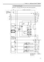
Page 57: ...Function 5 4 Circuit Diagrams EMERGENCY connector 45 5 4 Circuit Diagrams 5 4 1 Example 1 External emergency stop switch typical application ...

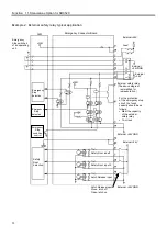
Page 58: ...Function 5 4 Circuit Diagrams EMERGENCY connector 46 5 4 2 Example 2 External safety relay typical application ...

Page 59: ...llowing table shows the applicable Drive Unit for the input output bit numbers Input bit number Output bit number Applicable Hardware 0 to 15 0 to 15 Standard Drive Unit DU1 16 to 31 16 to 31 Additional Drive Unit DU2 32 to 47 32 to 47 Additional Drive Unit DU3 Refer to the Function 7 Extension I O Board Optional for the specified model of an extension I O Board For cable wiring refer to the Funct...

Page 60: ...DC24V input The input bit numbers in the following diagrams presume the standard Drive Unit DU1 Typical Input Circuit Application 1 NPN type the standard for the regions outside Europe ditto ditto ditto ditto ditto Omit GND DC 1 Input No 0 to 3 common 2 Input No 0 3 Input No 1 4 Input No 2 5 Input No 3 26 Input No 4 to 7 common 27 Input No 4 28 Input No 5 2 2 kΩ 470 Ω ...

Page 61: ...pical Input Circuit Application 2 PNP type the European standard ditto ditto ditto ditto ditto Omit GND DC 1 Input No 0 to 3 common 2 Input No 0 3 Input No 1 4 Input No 2 5 Input No 3 26 Input No 4 to 7 common 27 Input No 4 28 Input No 5 2 2 kΩ 470 Ω ...

Page 62: ...pe the standard for the regions outside Europe CAUTION Be careful not to misconnect the output circuit because it has no protection circuit which protects the circuit from short circuit and reverse connection ditto ditto ditto ditto ditto 12 Output No 0 14 Output No 2 13 Output No 1 15 Output No 3 37 Output No 4 11 Output No 0 to 3 common 38 Output No 5 L L GND DC L Omit Jumper Settings for the NP...

Page 63: ... protects the circuit from short circuit and reverse connection ditto ditto ditto ditto ditto 11 Output No 0 to 3 common 13 Output No 1 12 Output No 0 14 Output No 2 36 Output No 4 7 common 15 Output No 3 38 Output No 5 L L GND DC L Omit 37 Output No 4 Jumper Settings for the PNP type Output Jumper No Setting JP4 5 9 10 14 15 19 20 24 25 1 2 3 5 4 6 JP6 11 16 21 26 Short JP7 12 17 22 27 Open JP8 1...

Page 64: ...Input No 3 30 Input No 7 6 Input common 8 to 11 31 Input common 12 to 15 7 Input No 8 32 Input No 12 8 Input No 9 33 Input No 13 9 Input No 10 34 Input No 14 10 Input No 11 35 Input No 15 11 Output common 0 to 3 36 Output common 4 to 7 12 Output No 0 37 Output No 4 13 Output No 1 38 Output No 5 14 Output No 2 39 Output No 6 15 Output No 3 40 Output No 7 16 Output common 8 to 11 41 Output common 12...

Page 65: ...3 7 Input common 4 to 7 32 NC 8 NC 33 Output common 4 to 7 9 Input No 4 34 Output No 4 10 Input No 5 35 Output No 5 11 Input No 6 36 Output No 6 12 Input No 7 37 Output No 7 13 Input common 8 to 11 38 NC 14 NC 39 Output common 8 to 11 15 Input No 8 40 Output No 8 16 Input No 9 41 Output No 9 17 Input No 10 42 Output No 10 18 Input No 11 43 Output No 11 19 Input common 12 to 15 44 NC 20 NC 45 Outpu...

Page 66: ...Function 6 3 Pin Assignments D I O Connector 54 ...

Page 67: ...d for the three drive units DU1 through DU3 The input and output bit s are assigned as follows For the Extension I O boards the I O Bit s start with 48 Input Bit Output Bit Applicable Hardware 0 to 15 0 to 15 Standard drive unit DU1 16 to 31 16 to 31 Additional drive unit DU2 32 to 47 32 to 47 Additional drive unit DU3 48 to 79 48 to 79 The 1st extension I O board 80 to 111 80 to 111 The 2nd exten...

Page 68: ...pen 1 JP1 JP2 A15 A8 A7 A3 0 0 0 0 0 1 1 1 0 0 0 0 0 0 7 0 0 When the Extension I O Board is extended an appropriate software settings must be done in addition to the below jumper settings For details about software settings refer to the SRC5 SPEL 95 User s Guide for a section 11 3 3 I O Board in the Function 11 Setup JP1 JP1 assigns I O addresses A15 through A8 16 15 14 13 12 11 10 9 8 7 6 5 4 3 ...

Page 69: ... I O number assignment depends on the SPEL 95 settings Input Voltage Range DC12 to 24V 10 On Voltage DC 10 8V MIN Off Voltage DC 5V MAX Input Current 10mA TYP at DC24V input Protected Extension I O Board Typical Input Circuit Application 1 NPN type ditto ditto ditto ditto ditto Omit GND DC 1 Input No 48 to 51 common 3 Input No 48 4 Input No 49 5 Input No 50 6 Input No 51 51 Input No 52 to 55 commo...

Page 70: ...d Extension I O Board Typical Input Circuit Application 2 PNP type the European standard ditto ditto ditto ditto ditto Omit GND DC 1 Input No 48 to 51 common 3 Input No 48 4 Input No 49 5 Input No 50 6 Input No 51 51 Input No 52 to 55 common 53 Input No 52 54 Input No 53 2 2 kΩ 470 Ω ...

Page 71: ...ber assignment depends on the SPEL 95 settings Protected Extension I O Board Typical Output Circuit Application 1 NPN type ditto ditto ditto ditto 27 Output No 48 28 Output No 49 29 Output No 50 30 Output No 51 77 Output No 52 25 Output No 48 to 51 common DC 26 Output No 48 to 51 common GND L L GND DC Omit Rated Output Voltage DC12V to 24V 10 Maximum Output current 250mA 1 output Output Driver N c...

Page 72: ...the European standard ditto ditto ditto ditto 27 Output No 48 28 Output No 49 29 Output No 50 30 Output No 51 77 Output No 52 25 Output No 48 to 51 common GND 26 Output No 48 to 51 common DC L L GND DC Omit Rated Output Voltage DC12V to 24V 10 Maximum Output current 250mA 1 output Output Driver P channel power MOS FET Saturation Voltage 1 0V or under ...

Page 73: ...1 JP2 A15 A8 A7 A3 0 0 0 0 0 1 1 1 0 0 0 0 0 0 7 0 0 When the Extension I O Board is extended an appropriate software settings must be done in addition to the below jumper settings For details about software settings refer to the SRC5 SPEL 95 User s Guide for the section 11 2 2 Remote in the Function 11 Setup JP1 JP1 assigns I O addresses A15 through A8 16 15 14 13 12 11 10 9 8 7 6 5 4 3 2 1 A15 A...

Page 74: ...L 95 settings Extension I O Board I O Typical Output Circuit Application 1 Output 48 to 55 Eight low numbers among thirty two bit numbers existing in one board are output CAUTION Be careful not to misconnect the output circuit because it has no protection circuit which protects the circuit from short circuit and reverse connection ditto ditto ditto ditto 27 Output No 48 28 Output No 49 29 Output N...

Page 75: ...it has no protection circuit which protects the circuit from short circuit and reverse connection ditto ditto ditto ditto ditto 33 Output No 56 35 Output No 58 34 Output No 57 36 Output No 59 83 Output No 60 32 Output No 56 59 common 84 Output No 61 L L GND DC L Omit Rated Output Voltage DC12V to 24V 10 Maximum Output Current 100mA 1 output Output Driver Photo coupler Saturation Voltage 1 6V or un...

Page 76: ...n C 56 to 59 32 Output common C GND 56 to 59 8 NC 33 Output No 56 9 Input No 56 34 Output No 57 10 Input No 57 35 Output No 58 11 Input No 58 36 Output No 59 12 Input No 59 37 Output common E DC 64 to 67 13 Input common E 64 to 67 38 Output common E GND 64 to 67 14 NC 39 Output No 64 15 Input No 64 40 Output No 65 16 Input No 65 41 Output No 66 17 Input No 66 42 Output No 67 18 Input No 67 43 Outp...

Page 77: ...3 58 NC 83 Output No 60 59 Input No 60 84 Output No 61 60 Input No 61 85 Output No 62 61 Input No 62 86 Output No 63 62 Input No 63 87 Output common F DC 68 to 71 63 Input common F 68 to 71 88 Output common F GND 68 to 71 64 NC 89 Output No 68 65 Input No 68 90 Output No 69 66 Input No 69 91 Output No 70 67 Input No 70 92 Output No 71 68 Input No 71 93 Output common H DC 76 to 79 69 Input common H...

Page 78: ...ut common C DC 56 to 59 8 NC 33 Output No 56 9 Input No 56 34 Output No 57 10 Input No 57 35 Output No 58 11 Input No 58 36 Output No 59 12 Input No 59 37 Output common E GND 64 to 67 13 Input common E 64 to 67 38 Output common E DC 64 to 67 14 NC 39 Output No 64 15 Input No 64 40 Output No 65 16 Input No 65 41 Output No 66 17 Input No 66 42 Output No 67 18 Input No 67 43 Output common G GND 72 to...

Page 79: ... 58 NC 83 Output No 60 59 Input No 60 84 Output No 61 60 Input No 61 85 Output No 62 61 Input No 62 86 Output No 63 62 Input No 63 87 Output common F GND 68 to 71 63 Input common F 68 to 71 88 Output common F DC 68 to 71 64 NC 89 Output No 68 65 Input No 68 90 Output No 69 66 Input No 69 91 Output No 70 67 Input No 70 92 Output No 71 68 Input No 71 93 Output common H GND 76 to 79 69 Input common H...

Page 80: ...1 100 51 An internal power is not supplied to the Extension I O connector Therefore an external power source must be supplied 7 5 2 Extension I O Connector Cable The Extension I O connector cable is an optional part It has a 100 pin connector on one end and two 50 pin connectors on the other end The Extension I O board 100 pin 50 pin 2 1 2 2 m ...

Page 81: ... to 55 32 Output common B DC 52 to 55 8 NC 33 Output common B GND 52 to 55 9 Input No 52 34 Output No 52 10 Input No 53 35 Output No 53 11 Input No 54 36 Output No 54 12 Input No 55 37 Output No 55 13 Input common C 56 to 59 38 Output common C DC 56 to 59 14 NC 39 Output common C GND 56 to 59 15 Input No 56 40 Output No 56 16 Input No 57 41 Output No 57 17 Input No 58 42 Output No 58 18 Input No 5...

Page 82: ...common F GND 68 to 71 9 Input No 68 34 Output No 68 10 Input No 69 35 Output No 69 11 Input No 70 36 Output No 70 12 Input No 71 37 Output No 71 13 Input common G 72 to 75 38 Output common G DC 72 to 75 14 NC 39 Output common G GND 72 to 75 15 Input No 72 40 Output No 72 16 Input No 73 41 Output No 73 17 Input No 74 42 Output No 74 18 Input No 75 43 Output No 75 19 Input common H 76 to 79 44 Outpu...

Page 83: ...GND 52 to 55 8 NC 33 Output common B DC 52 to 55 9 Input No 52 34 Output No 52 10 Input No 53 35 Output No 53 11 Input No 54 36 Output No 54 12 Input No 55 37 Output No 55 13 Input common C 56 to 59 38 Output common C GND 56 to 59 14 NC 39 Output common C DC 56 to 59 15 Input No 56 40 Output No 56 16 Input No 57 41 Output No 57 17 Input No 58 42 Output No 58 18 Input No 59 43 Output No 59 19 Input...

Page 84: ... common F DC 68 to 71 9 Input No 68 34 Output No 68 10 Input No 69 35 Output No 69 11 Input No 70 36 Output No 70 12 Input No 71 37 Output No 71 13 Input common G 72 to 75 38 Output common G GND 72 to 75 14 NC 39 Output common G DC 72 to 75 15 Input No 72 40 Output No 72 16 Input No 73 41 Output No 73 17 Input No 74 42 Output No 74 18 Input No 75 43 Output No 75 19 Input common H 76 to 79 44 Outpu...

Page 85: ...O Connector and Function 7 Extension I O Board Optional in this manual For details about communication with external equipment refer to the SRC5 SPEL 95 User s Guide for a section 7 3 Remote Setting in the 7 Communication with External Equipment CAUTION When using I O at the remote setup always make sure before allowing current to flow that the cable connections match to the pin assignments Failur...

Page 86: ... for continuous execution of all tasks 2 PAUSE Input for pausing the Controller RESET Input for releasing the emergency stops and errors and for interrupting all tasks including background tasks Grp No 0 Grp No 1 Grp No 2 Grp No 3 Specifies the group number of the project for enabling START input 4 RECOVER Input for canceling the emergency stop status and for returning all manipulators to the stat...

Page 87: ...0 0 1 0 6 1 0 1 0 7 0 1 1 0 8 1 1 1 0 9 0 0 0 1 10 1 0 0 1 11 0 1 0 1 12 1 1 0 1 13 0 0 1 1 14 1 0 1 1 15 0 1 1 1 16 1 1 1 1 0 OFF 1 ON 4 Specify the group number with Grp No 0 3 4 bit referring to the table below Specified Group No Grp No 0 Grp No 1 Grp No 2 Grp No 3 0 0 0 0 0 1 1 0 0 0 2 0 1 0 0 3 1 1 0 0 4 0 0 1 0 5 1 0 1 0 6 0 1 1 0 7 1 1 1 0 8 0 0 0 1 9 1 0 0 1 10 0 1 0 1 11 1 1 0 1 12 0 0 1 ...

Page 88: ...anipulators as determined by input of the Sel Mnp signal MCALed Outputs the MCAL initializing a manipulator to the mechanical origin position status Executed ON Outputs the status of the Manipulators as determined by input of the Sel Mnp signal HOME Outputs the home position status Outputs the status of the Manipulators as determined by input of the Sel Mnp signal Mnp No 0 Mnp No 1 Mnp No 2 Mnp No...

Page 89: ...mode status ON in the AUTO mode OFF in the PROGRAMMING mode ATTEND mode Outputs the operation mode status ON in the ATTEND operation mode OFF in the NORMAL operation mode READY Outputs the READY status of the Controller ON in the READY and RESET status 3 4 Refer to the tables in the Function 8 1 1 Input Signal ...

Page 90: ...rts for the timing interrelation when you enter an input signal In designing avoid simultaneous entries as much as possible to prevent errors since the remote signal value is entered in pulse The pulse width of an input signal must be 10 or more millisecond to avoid chattering 8 2 2 Timing Diagram for Operation Execution Sequence Power status Output HOME Output Mnp No output Motor ON Input Motor O...

Page 91: ...2 Select the number 1 The duration varies depending on the Quick Pause QP setting and the program s operating status at the time of Pause input 2 It is the timing of READY output input when using the background task 8 2 4 Timing Diagram for Safety Door Input Sequence START monitor Output In PAUSE Output Safety Door Output Safety Door Input Safety Door Latch Release Input START Input This timing de...

Page 92: ...Emergency Stop Output RESET Input 1 Emergency Stop Input 20msec 500msec 10msec 1 It is the timing of READY output input when using the background task 8 2 6 Timing Diagram for Error Generating Sequence START monitor Output RESET Output 1 Error Output RESET Input 1 500msec 30msec Error occurs 1 It is the timing of READY output input when using the background task ...

Page 93: ...uded in the standard SRC520 model Prepare them as necessary The cable must be twisted shield pair Clamp the shield on the hood to prevent noise 9 1 1 Pin Assignments Pin assignments for RS 232C connector are as follows Pin No Abbr Signal Name Signal Direction 1 CD Data carrier detect Input 2 RD Receive data Input 3 SD Send data Output 4 ER Terminal ready Output 5 SG Signal ground 6 DR Data set rea...

Page 94: ...gnal Name Pin No Pin No Signal Name SD 3 2 SD RD 2 3 RD SG 5 7 SG RS 7 4 RS CS 8 5 CS DR 6 6 DR CD 1 8 CD ER 4 20 ER Clamp Hood 1 FG Example 2 H W Flow Control Control Unit Peripheral equipment Signal Name Pin No Pin No Signal Name SD 3 2 SD RD 2 3 RD SG 5 7 SG RS 7 4 RS CS 8 5 CS DR 6 6 DR CD 1 8 CD ER 4 20 ER Clamp Hood 1 FG ...

Page 95: ...ake sure that the settings on the following parameters on both units match You may use either SETCOM command or go to Setting of a Robot Controller COM Port to set up the following parameters Port Baud Rate Data Bit Length Stop Bit Parity Terminator H W Flow Control S W Flow Control Timeout sec For details on the set up procedure and communication commands refer to the SRC5 SPEL 95 User s Guide fo...

Page 96: ...Function 9 2 Preparation for Communication RS 232C Settings 84 ...

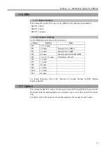
Page 97: ... an additional MIB is installed the software needs to be re setup accordingly in addition to the jumper settings For further details refer to the SRC5 SPEL 95 User s Guide for a section 11 3 Setting Up the Hardware in the 11 Setup JP1 factory set and fixed 1 2 3 4 5 6 Short JP2 Set up the Periodic Interrupt Level for the first MIB only This setting is not necessary for the 2nd or the 3rd MIB Inter...

Page 98: ...MIB 340 35F For the third MIB 360 37F 380 39F 3A0 3BF 3C0 3DF 3E0 3FF Short JP6 JP7 factory set and fixed 1 2 3 4 Short JP8 When the manipulator s axes configuration is such as to require two or more Drive Units these Drive Units need to be defined as either master or slave The normal settings are open for all of them Setting 1 2 3 4 5 6 Master 1ms signal Master XF signal Slave Short JP9 JP10 Setu...

Page 99: ...op input and Safety Door input by connecting an Extension Emergency Connector Unit to the Control Unit The Stand alone Option has been available from SPEL95 Ver2 5 If necessary refer to the Function 2 3 Control Unit for functions of the Control Unit 11 2 System Configuration SRC520 Control Unit OP500 Camera Solenoid Valve Driver Motor Sensor 11 3 Installation When installing the Control Unit it mu...

Page 100: ...ication Voltage When the power supply voltage switch is set at 115 side AC100V to AC120V When the power supply voltage switch is set at 230 side AC200V to AC240V Frequency 50 60Hz Momentary Power Interrupt Less than 10msec Power Consumption 300W The monitor is not connected Peak Current Approximately 40A at AC200V Leakage Current 3 5mA max 11 5 Extension Emergency Connector Unit An Extension Emerg...

Page 101: ... Connects an extension emergency connector board with the MIB Motion Connector Cover Prevents the use of a MIB motion connector When using the Control Unit only be sure to place this Motion Connector Cover to avoid connecting with the Drive Unit 11 5 3 Safety Door Switch and Emergency Stop Switch For details about functions and connection of the Safety Door switch Emergency Stop switch and Latch R...

Page 102: ... 1 The Emergency Stop condition is output via relay contact when it is open it is normally closed 2 It becomes an error if the input values from the Safety Door 1 and Safety Door 2 are apart by two or more seconds They must be connected to the same switch with two contacts Emergency Stop switch output rated load DC 30V 1A or under 1 2 11 12 pin Emergency Stop rated input voltage range Emergency St...

Page 103: ... typical application Latch Release input Close latch off Open latch on Emergency Stop switches of an operating unit Emergency Stop detection Emergency Stop condition control Safety Door detection Safety Door input 1 Safety Door input 2 Latch Release input External 24VGND External 24V Emergency Stop detection ...

Page 104: ...Door input1 Safety Door input 2 Latch Release input External 24VGND Emergency Connector Board External 24V Fuse External 24VGND External safety relay The above diagram is simplified for representation For the protection of the emergency stop circuit the fuse s capacity should be as follows Meet the capacity of the external safety relay 1A or less External 24V External 24VGND Emergency Stop conditi...

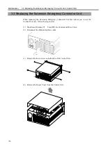
Page 105: ...short Interrupt level IRQ5 JP4 All open Memory address D8000 DFFF JP5 1 2 3 4 5 6 short I O address 300 31F JP6 1 2 short JP7 1 2 short JP8 All open JP9 1 2 short JP10 1 2 short JP11 All open For jumper functions refer to the Function 10 Jumper Settings for MIB Motion Interface Board 11 7 Option The options for SRC520 such as the Operation Units JP500 and OP500 Extension I O Board and Pulse Genera...

Page 106: ...Function 11 Stand alone Option for SRC520 94 ...

Page 107: ...95 Maintenance The manual herein explains the maintenance procedure for each unit in the robot controller SRC 520 ...

Page 108: ...Maintenance 96 ...

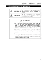
Page 109: ...nnel are those who are certified trainees of the government sponsored training courses for safety operation of industry robots or those who have completed the manufacturer or dealer s introductory and maintenance training courses held on a regular basis Always make sure before performing any maintenance procedure that the main power is turned OFF and that the high voltage charged area is completel...

Page 110: ... damage the contained data Make sure that the wattage of the new Motor Drive module is correct When the inappropriate wattage module is connected with the Drive Unit the robot may not function properly or may be damaged Check on the Connection Check Label DU number at Control Unit and Signature Labels at Drive Unit Manipulator when connecting those units If those units are misconnected the robot m...

Page 111: ...der Manipulator Drive Unit Manipulator s axes configuration Encoder type ABS INC CTGAIN CTOFFSET Motor driver wattage Jumper settings of MIB Memory I O address Drive Unit No Setting data Manipulator hardware Cable length Output voltage Motor wattage Motor driver wattage Mount or Unmount 1 or 2 Drive Unit Manipulator numbers in sample configuration Mnp1 Mnp2 Mnp3 Mnp6 Mnp4 Mnp5 SPEL 95 Encoder Volt...

Page 112: ...boards refer to the manual attached to each board Control Unit Input output Equipment Total input output included 128 Input output Equipment Input 32 Output 32 Drivers Computer MIB MIB MIB Optional Boards Pulse Generating Board Set the jumper for I O address Extension I O Board Set the jumper for I O address Remote I O Board Set the jumper for I O address and the number of I O Motors of manipulato...

Page 113: ...enance 3 1 Overview Control Unit 101 3 Control Unit 3 1 Overview The Control Unit internal layout CPU board Switching Power Supply MIB CD ROM Drive System Panel FDD upper HDD lower Filter Fan Drive Bay Unit ...

Page 114: ... is suspected to be defective replace the board by following the steps below 1 Shut down Windows 95 Turn OFF the Control and Drive Units 2 Disconnect the Motion Interface cable 3 Remove the four screws on both sides of the Control Unit 4 Remove the Upper Cover from the Control Unit ...

Page 115: ...ve two affixing screws and then take the metal fitting off from the board Metal Fitting 6 Remove the affixing screw from MIB and remove the MIB out of the slot in the Control Unit 7 Disconnect the cable from MIB by releasing the connector lock as shown below ...

Page 116: ... same as on the old board Refer to the Function 10 Jumper Settings for MIB Motion Interface Board for details of the jumper functions 9 Connect the cable from the System panel to the new MIB 10 Mount the new MIB onto the option slot in the Control Unit and fasten the screw to secure the new board ...

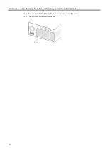
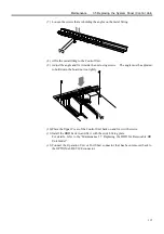
Page 117: ...zes to accommodate different board sizes Select the one that fits 12 Affix the metal fitting to the Control Unit 13 Adjust the angle and fix it inside the unit using screws The angle must be adjusted to hold down the board not too tightly 14 Place the Upper Cover of the Control Unit back on and secure it with the screws 15 Connect the Motion Interface cable ...

Page 118: ...Unit When replacing the Extension Emergency Connector Unit that allows you to use the Control Unit only follow the steps below 1 Shut down Windows 95 Turn OFF the Control and Drive Units 2 Disconnect the Motion Interface cable 3 Remove the four screws on both sides of the Control Unit 4 Remove the Upper Cover from the Control Unit ...

Page 119: ... the Extension Emergency Connector Board and remove the Board 8 Mount a new Extension Emergency Connector Board onto the slot and fasten the screw to secure the new board 9 Connect the MIB to the Extension Emergency Connector Board with a cable 10 Loosen the screws that are holding the angles on the metal fitting 11 Affix the metal fitting to the Control Unit 12 Adjust the angle and fix it inside ...

Page 120: ...Maintenance 3 3 Replacing the Extension Emergency Connector Unit Control Unit 108 13 Place the Control Unit Cover back on and secure it with the screws 14 Connect the Motion Interface cable ...

Page 121: ...t 109 3 4 Replacing an Optional Board When replacing an optional board s refer to the Maintenance 3 2 Replacing the MIB and follow the procedure If there is any jumper set on the old board it must be set on the new board exactly the same as on the old board ...

Page 122: ...lows 3 5 1 Removable HD Unit Model Removal 1 Shut down Windows 95 and then turn OFF the power on both the Control and Drive Units 2 Disconnect the Operation Unit or Port Short connector from the OPTIONAL DEVICE connector 3 Remove the HDD For the procedure refer to the Maintenance 3 7 Replacing the HDD for Removable HD Unit Model 4 Remove the four screws on both sides of the Control Unit 5 Remove t...

Page 123: ...connector lock as shown below 8 Disconnect any cables that are connected to the Drive Bay Unit DC ROM drive FDD and HDD mounting case CAUTION Do not shock shake or drop the HDD FDD and CD ROM drive When these disk drives are shocked physically it may damage the contained data 9 Unscrew all the mounting screws on the Drive Bay Unit to remove the unit Drive Bay Unit FDD HDD mounting case CD ROM driv...

Page 124: ...ystem Panel Control Unit 112 10 Unscrew the mounting screws on the System Panel and remove it from the Drive Bay Unit 11 Remove the two screws on the HDD mounting case and remove it from the System Panel Screw Screw HDD mounting case ...

Page 125: ...Attach the HDD mounting case to a new system panel with the four screws Match the faces of the case and the system panel to flatten 2 Install the System Panel in the Drive Bay Unit and secure it with the screws Face of the system panel Face of the HDD mounting case Screw Screw ...

Page 126: ...l the Drive Bay Unit and fix it with the screws 4 Connect the cables for the Drive Bay Unit HDD mounting case CD ROM drive and FDD back 5 Connect the cable from the System Panel to the MIB 6 Attach the MIB on the option slot in the Control Unit and fix it with the screw ...

Page 127: ...using screws The angle must be adjusted to hold down the board not too tightly 10 Place the Upper Cover of the Control Unit back on and fix it with screws 11 Install the HDD back in and fix it with the switch fixing plate For details refer to the Maintenance 3 7 Replacing the HDD for Removable HD Unit Model 12 Connect the Operation Unit or Port Short connector that has been removed back to the OPT...

Page 128: ...moval 1 Shut down Windows 95 and then turn OFF the power on both the Control and Drive Units 2 Disconnect the Operation Unit or Port Short connector from the OPTIONAL DEVICE connector 3 Remove the four screws on both sides of the Control Unit 4 Remove the Upper Cover from the Control Unit ...

Page 129: ... HDD CD ROM drive and FDD Unscrew all the mounting screws on the Drive Bay Unit to remove the unit 6 Unscrew the mounting screws on the HDD and remove the HDD from the Drive Bay Unit CAUTION Do not shock shake or drop the HDD FDD and CD ROM drive When these disk drives are shocked physically it may damage the contained data ...

Page 130: ...Maintenance 3 5 Replacing the System Panel Control Unit 118 7 Unscrew the mounting screws on the System Panel and remove it from the Drive Bay Unit 8 Remove the flat cable connecting to the MIB ...

Page 131: ...at cable of the new System to the MIB 2 Install the System Panel in the Drive Bay Unit and secure it with the screws 3 Affix the four mounting screws on the HDD temporarily Match the screws on the upper two through holes and fasten to secure the HDD position Tighten the remaining two screws ...

Page 132: ...t the cables for the Drive Bay Unit HDD CD ROM drive and FDD back 6 Place the Upper Cover of the Control Unit back on and fix it with the screws Connect the Motion Interface cable PC Power cable and Monitor cable 7 Connect the Operation Unit or Port Short connector that has been removed back to the OPTIONAL DEVICE connector ...

Page 133: ... Control and Drive Units 2 Open the front panel door 3 Pull the Fan Filter case frontward by holding its tab while sliding it to the right 4 Remove the filter from the filter case 5 Clean or replace the filter When you clean the filter vacuum the dust with a vacuum cleaner 6 Place the clean filter back in the filter case The filter must be securely place under the four hooks on the edges of the ca...

Page 134: ... refer to the 3 5 2 Built in HDD Model in the Maintenance 3 5 Replacing the System Panel 1 Shut down Windows 95 Turn OFF the power on both the Control and Drive Units 2 Open the front panel door 3 Loosen the screw on the switch fixing plate and remove the plate from the HDD 4 Move the lock switch right 5 Pull out the HDD forward 6 Install a new HDD and fix it with the switch fixing plate Refer to ...

Page 135: ... Connector Regeneration Module Motor Driver Modules M C Signal Connector Motion Connector Switching Power Supply Module Main Power Supply Circuit Module Drive Main Board DMB Drive Power Board DPB Rear Panel Fan Filter Motor Power Module Front Panel Axis Axis Axis Axis 1 2 3 4 ...

Page 136: ...n assignments for the M C power connector M C signal connector and Motion connector respectively As for the pin assignments of the connectors not covered in this section refer to the function volume in this manual 4 2 1 M C Power Pin No Signal Pin No Signal 1 1U 9 3W 2 4V 10 2U 3 1V 11 NC 4 4U 12 NC 5 SHIELD 13 3V 6 1W 14 2V 7 4W 15 3U 8 NC 16 2W FGND ...

Page 137: ...5V 32 EMB1 57 1A 8 EG 33 24V 58 1B 9 3A 34 RG 59 1Z 10 3B 35 EG 60 1S 11 3Z 36 4A 61 HCOM 12 3S 37 4B 62 ENC 5V 13 3HOME 38 4Z 63 NC 14 ENC 5V 39 4S 64 NC 15 EG 40 NC 65 NC 16 2A 41 ENC 5V 66 EMB2 17 2B 42 EG 67 24V 18 2Z 43 3A 68 RG 19 2S 44 3B 20 2HOME 45 3Z 21 ENC 5V 46 3S 22 EG 47 NC 23 1A 48 ENC 5V 24 1B 49 EG 25 1Z 50 2A The Drive Unit and Manipulator s pin numbering layout differs one is li...

Page 138: ...0 INT4 11 EA7 51 E_SW11 91 READY 12 EA7 52 GND 92 READY 13 EA5 53 EA14 93 E_STOP003 14 EA5 54 EA14 94 E_STOP004 15 EA3 55 EA12 95 NC 16 EA3 56 EA12 96 NC 17 EA1 57 EA10 97 NC 18 EA1 58 EA10 98 E_SW22 19 BANK2 59 EA8 99 GND 20 BANK2 60 EA8 100 E_SW12 21 BANK0 61 EA6 22 BANK0 62 EA6 23 GND 63 EA4 24 GND 64 EA4 25 MRD 65 EA2 26 MRD 66 EA2 27 EIOR 67 EA0 28 EIOR 68 EA0 29 ED7 69 BANK1 30 ED7 70 BANK1 ...

Page 139: ...Maintenance 4 3 Drive Unit Drive Unit 127 4 3 Drive Unit 4 3 1 System Configuration ...

Page 140: ...the Drive Unit for each module to be installed Module Description Main Power Supply Circuit The module incorporates the following modules the AC Power Input Motor Power and Switching Power Supply Motor Power The module rectifies AC200V or the local equivalent and outputs the DC power to the motor Switching Power Supply This module outputs DC24V rectified from AC200V or the local equivalent as the ...

Page 141: ...ollowing the steps as described below 1 Turn ON the Drive Unit s 2 Check on the Drive Unit s front panel if the POWER LED green is ON If this lamp is either OFF or dim suspect that the 24V power output is not normal 3 Check on the Drive Unit s front panel to make sure that the LED green on the left of and behind the ERROR LED red is ON When this lamp is OFF either the 24V or 5V power output may no...

Page 142: ...data beside the Signature label indicates specific information to each Motor Driver module In order to optimize the Control Unit s control over the Manipulator the exact same values as indicated here must be set up in the Control Unit after the motor Driver module is replaced There are two kinds of CT data as follows 4B display the information on CT OFFSET 4D display the information on CTGAIN The ...

Page 143: ...isconnect all the cables from the back of the Drive Unit 3 Wait for about 1 minute until the high voltage is completely discharge Remove the Upper Cover by unscrewing the eight set screws as in the figure below PO WE R DR IVE UN IT SRC520 EPSON 1 2 ERRO R RUN E STO P POWE R POWE R MOTO R DRIVE UNIT 4 Check to make sure that the LED 9 orange on the DPB is OFF Wait until the light is OFF because the...

Page 144: ... projections on both sides of the connector to disconnect the cable smoothly 7 Connect the cable to a new Motor Driver module 8 Press down the module carefully and gradually to match the connectors on DPB and DMB 9 Secure the new Motor Driver module and fix the Upper Cover with two screws 1 Compress 2 Pull out 8 DPB connector 8 DMB connector 9 M4 screws ...

Page 145: ... the cables are connected correctly 2 Turn ON the Control and Drive Units and start up Windows 95 and SPEL 95 3 Execute Setup Hardware Setting from menu bar to display SPEL 95 Hardware Settings dialog 4 Select MIB tab to show the MIB panel 5 Click the Setup button for the appropriate Drive Unit to show Drive Unit Settings dialog 6 Enter the CT GAIN and CT OFFSET values for the new Motor Driver mod...

Page 146: ...ctor to connect the Signal cable of the Regeneration module J21 The connector to connect the Power Supply cable from the Motor Power module J22 to 25 The connectors to supply motor power to the Motor Driver module J26 The connector to supply motor power to the Regeneration module Volume Volume No Function VR1 The control knob to adjust the Encoder Power Supply voltage VR2 The control knob to adjus...

Page 147: ...ive Unit detects an error LED4 RUN Lights while the CPU of the Drive Unit is operating normally LED5 E STOP Lights when in the emergency stop condition LED6 MOTOR POWER Lights when the motor power is ON Motor Power The DC power supply that inputs to the Motor Driver module to drive the motor This DC power is generated by regulating AC200V or the local equivalent power LED7 POWER Lights when the Dr...

Page 148: ...e longest motor cable in the Manipulator As for which pins to measure refer to the Manipulator manual 3 If the encoder voltage is not within the range of 4 9V to 5 2V adjust it as follows 4 Remove the Upper Cover of the Drive Unit by taking out the eight screws 5 If the measured voltage is lower than 4 9V turn the VR1 on DPB knob direction by 1 2 track to increase the voltage If the measure voltag...

Page 149: ...as VCC and GND near J16 connector on the DPB 6 If the 5V voltage is not within the range of 4 9V to 5 2V adjust the voltage as follows 7 If the measured voltage is lower than 4 9V turn the VR2 on DPB knob direction by 1 2 track to increase the voltage If the measure voltage is higher than 5 2V turn the VR2 knob direction by 1 2 track to lower the voltage 8 Repeat the step 5 to ensure that the volt...

Page 150: ...5V voltage for the Motor Driver module TP3 5V 5V voltage for the Motor Driver module TP4 24V 24V output voltage of the Switching Power Supply module TP5 5 6V Encoder power supply voltage TP6 GND GND for TP1 through TP5 LED No Description 1 ON while the power for Encoder is output 2 ON while the Manipulator s electromagnetic brake is released CN5 CN6 CN7 CN8 LED2 LED1 CN11 The through holes test pi...

Page 151: ...the Drive Unit as shown below AC OUTLE T AC 200 22 0V 3A INPUT AC 200 22 0V M C POWE R 5 Make sure that the LED 9 orange on the DPB is OFF The condenser is not completely discharged while this lamp is ON Make sure to wait until the lamp turns OFF 6 As shown below remove the set screws on the motor drivers for four axes in the Drive Unit PO WE R DR IVE UN IT SRC520 EPSON 1 2 ERRO R RUN E STO P POW ...

Page 152: ...ta and the wattage so that the settings for the Motor Driver module remain the same 10 Disconnect the flat cable CN11 that connects to DPB 11 Disconnect all cables connected to the DMB from the back of the Drive Unit 12 Remove six set screws securing DMB in the Drive Unit 13 Replace the DMB by a new one 14 Fit in the new DMB and fix it with six set screws loose enough so that it can still be moved...

Page 153: ...hten the six set screws that are still loose in the step 14 17 Connect the flat cable CN11 18 If the Regeneration module has been removed in the step 7 reattach it with referring the steps 6 and 7 described in the Maintenance 4 8 2 Replacing a Regeneration Module 19 Place the Motor Drivers and the Upper Cover back on ...

Page 154: ...d below 1 Shut down Windows 95 and turn OFF the Control and Drive Units 2 Wait for about 1 minute until the high voltage is discharged Then remove the Front Panel as shown below Regarding the top center screw the panel can be removed by just loosening it Be careful not to pull the Front Panel too tightly because the power cable of the fan is connected to DPB Loosen the top center screw M3 crown wa...

Page 155: ...make sure that the Fan operates normally 4 7 3 Replacing the Fan Replace the fan by following the steps described below 1 Shut down Windows 95 and turn OFF the Control and Drive Units 2 Wait for about 1 minute until the high voltage is discharged Then remove the Front Panel as shown below Regarding the top center screw the panel can be removed by just loosing it Be careful not to pull the Front Pa...

Page 156: ...ndard fan J17 for the optional fan on the DPB 4 Remove the four set screws that hold the Cooling Fan in place 5 Install a new Cooling Fan and connect the cable of the fan to the connector on the DPB 6 Reattach the Front Panel 7 Turn ON the Drive Unit and make sure that the new Cooling Fan runs properly J17 J18 M3 screws ...

Page 157: ...ator s is are operating If a Regeneration module is installed the JP1 on the DPB Drive Power Board must be open 4 8 2 Replacing a Regeneration Module Replace the Regeneration module by following the steps described below 1 Shut down Windows 95 and turn OFF the Control and Drive Units 2 Disconnect all the cables from the back of the Drive Unit 3 Wait for about 1 minute until the high voltage is com...

Page 158: ...nnect the connector J20 from the DPB 7 Connect the J20 connector of a new Regeneration module to DPB 8 The new Regeneration module must be pushed in carefully while making it sure that the J26 connector engages properly 9 Affix the Regeneration module securely Place the Upper Cover back on J20 J26 J20 J26 ...

Page 159: ...hose do not match causing to activate an unintended robot 2 Turn ON both the Drive Unit and Control Unit Launch SPEL 95 During this process watch and monitor the LED status against the following list Drive Unit Front Panel LED From power on to SPEL 95 launch While running the SPEL 95 POWER LED The lamp must be ON if the system is operating properly When the light is OFF suspect either the input ou...

Page 160: ...nder normal conditions It must turn ON when there is a system error 7 segment When the main power is turned ON 8 lights up momentarily and goes OFF The displayed data must change from 0 in order to indicate the system condition that is checked at the beginning of SPEL 95 launch The lamp is OFF under normal conditions In case of system error it must display the status of the error by the designated...

Page 161: ...SU3C 1 SR520DRU007 R12R520DRU007 Motor Driver 750W CACR 08 SU3C 1 SR520DRU008 R12R520DRU008 Regeneration Module Board No SKP375 1 SR500DRU011 R13R500DRU011 Cooling Fan 109P0924H402 DC24V 1 SR500DRU012 R13R500DRU012 Fan Filter for Drive Unit 1 SR500CUP012 R12R500CUP012 Fan Filter for Control Unit 1 SR520CUP001 R12R520CUP001 MIB Motion Interface Board Board No SKP372 1 1 R220500010020 MIB Motion Int...

Page 162: ...n I O Board Board No SKP349 1 SR500PLS003 R13R500PLS003 Pulse Generating Board C 863 1 SR500RIO001 R13R500RIO001 Remote I O Board SL PCAT 1 SR500NET001 R13R500NET001 Ethernet Board 3C509B TPO 1 R220500010010 Emergency Connector Unit 6 Board No SKP393 1 1 It will be available according to the jumper settings 2 It is available to a Control Unit with a system panel for removable HD unit model 3 Pleas...

Reviews: