Maintenance 4.3 Drive Unit (Drive Unit)
129
4.3.3 Inspecting a Switching Power Supply Module
The Switching Power Supply module rectifies AC200V (or the local equivalent) and
outputs DC24V. The DC24V is converted by the DPB to supply power to: VCC (
+
5V),
the motor driver (
+
5V) and the encoder (5V).
Inspect the Switching Power Supply module by following the steps as described below:
(1) Turn ON the Drive Unit(s).
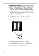
(2) Check on the Drive Unit’s front panel if the POWER LED (green) is ON.
If this lamp is either OFF or dim, suspect that the
+
24V power output is not normal.
(3)
Check on the Drive Unit’s front panel to make sure that the LED (green) on the left
of and behind the ERROR LED (red) is ON. When this lamp is OFF, either the
+
24V or
+
5V power output may not be normal, or the
+
24V power voltage may be
too low.
DRIVE UNIT
(3) LED (green)
1 2
ERROR
RUN
E-STOP
POWER
POWER
MOTOR
(2) POWER LED (green)
Summary of Contents for SRC520
Page 1: ...SRC520 Rev 4 EM015C868F ROBOT CONTROLLER ...
Page 2: ...ROBOT CONTROLLER SRC520 Rev 4 ...
Page 13: ...Function The manual herein explains in detail the functions of the robot controller SRC520 ...
Page 14: ...Function 2 ...
Page 29: ...Function 2 3 Control Unit Part Names and Functions 17 2 3 4 Dimensions mm ...
Page 35: ...Function 2 4 Drive Unit Part Names and Functions 23 2 4 5 Dimensions mm ...
Page 36: ...Function 2 4 Drive Unit Part Names and Functions 24 ...
Page 50: ...Function 3 5 Noise Countermeasures Installation 38 ...
Page 66: ...Function 6 3 Pin Assignments D I O Connector 54 ...
Page 96: ...Function 9 2 Preparation for Communication RS 232C Settings 84 ...
Page 106: ...Function 11 Stand alone Option for SRC520 94 ...
Page 108: ...Maintenance 96 ...
Page 139: ...Maintenance 4 3 Drive Unit Drive Unit 127 4 3 Drive Unit 4 3 1 System Configuration ...

