Function 1. For Safety
3
1. For Safety
1.1 Safety Precautions
WARNING
This sign indicates that a danger of serious injury or death
will exist if instructions there under are not followed.
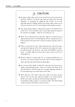
CAUTION
This sign indicates that ignoring the instructions there under
may cause harm to people or physical damage to equipment
and facilities.
WARNING
Do not open the cover(s) of the Control and Drive Units except while
maintaining them. Because of the high voltage charger inside the Control
Unit and Drive Unit, there is a risk of fatal electrical shock even when its
main power is OFF.
If it is necessary to change the plug to fit the outlet in your factory, be certain
to connect the earth wire of the AC power cable colored green/yellow to the
earth terminal of the factory power supply. The equipment must be
grounded properly at all times to avoid the risk of electric shock. Always
use a power plug. Never connect the controller directly to the factory power
supply.
Make sure that the power to the Control Unit and Drive Unit is turned OFF
before connecting or disconnecting any cables. Failure to do so may cause
electric shock and may damage the units.
The interlock of the Safety Door must be functioning when the system is
operated. It is dangerous to operate the system unless the Safety Door
switch is in a completely functioning condition.
Do refer to the typical application diagram in “Function 5.4 Circuit Diagrams”
in this manual when wiring to the EMERGENCY connector so that it should
not dysfunction the emergency stop input at the Optional Units via the
OPTIONAL DEVICE connector.
Summary of Contents for SRC520
Page 1: ...SRC520 Rev 4 EM015C868F ROBOT CONTROLLER ...
Page 2: ...ROBOT CONTROLLER SRC520 Rev 4 ...
Page 13: ...Function The manual herein explains in detail the functions of the robot controller SRC520 ...
Page 14: ...Function 2 ...
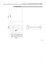
Page 29: ...Function 2 3 Control Unit Part Names and Functions 17 2 3 4 Dimensions mm ...
Page 35: ...Function 2 4 Drive Unit Part Names and Functions 23 2 4 5 Dimensions mm ...
Page 36: ...Function 2 4 Drive Unit Part Names and Functions 24 ...
Page 50: ...Function 3 5 Noise Countermeasures Installation 38 ...
Page 66: ...Function 6 3 Pin Assignments D I O Connector 54 ...
Page 96: ...Function 9 2 Preparation for Communication RS 232C Settings 84 ...
Page 106: ...Function 11 Stand alone Option for SRC520 94 ...
Page 108: ...Maintenance 96 ...
Page 139: ...Maintenance 4 3 Drive Unit Drive Unit 127 4 3 Drive Unit 4 3 1 System Configuration ...

