Maintenance 4.6 DMB (Drive Unit)
138
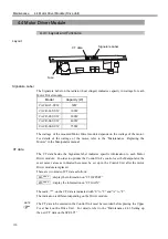
4.6 DMB (Drive Main Board)
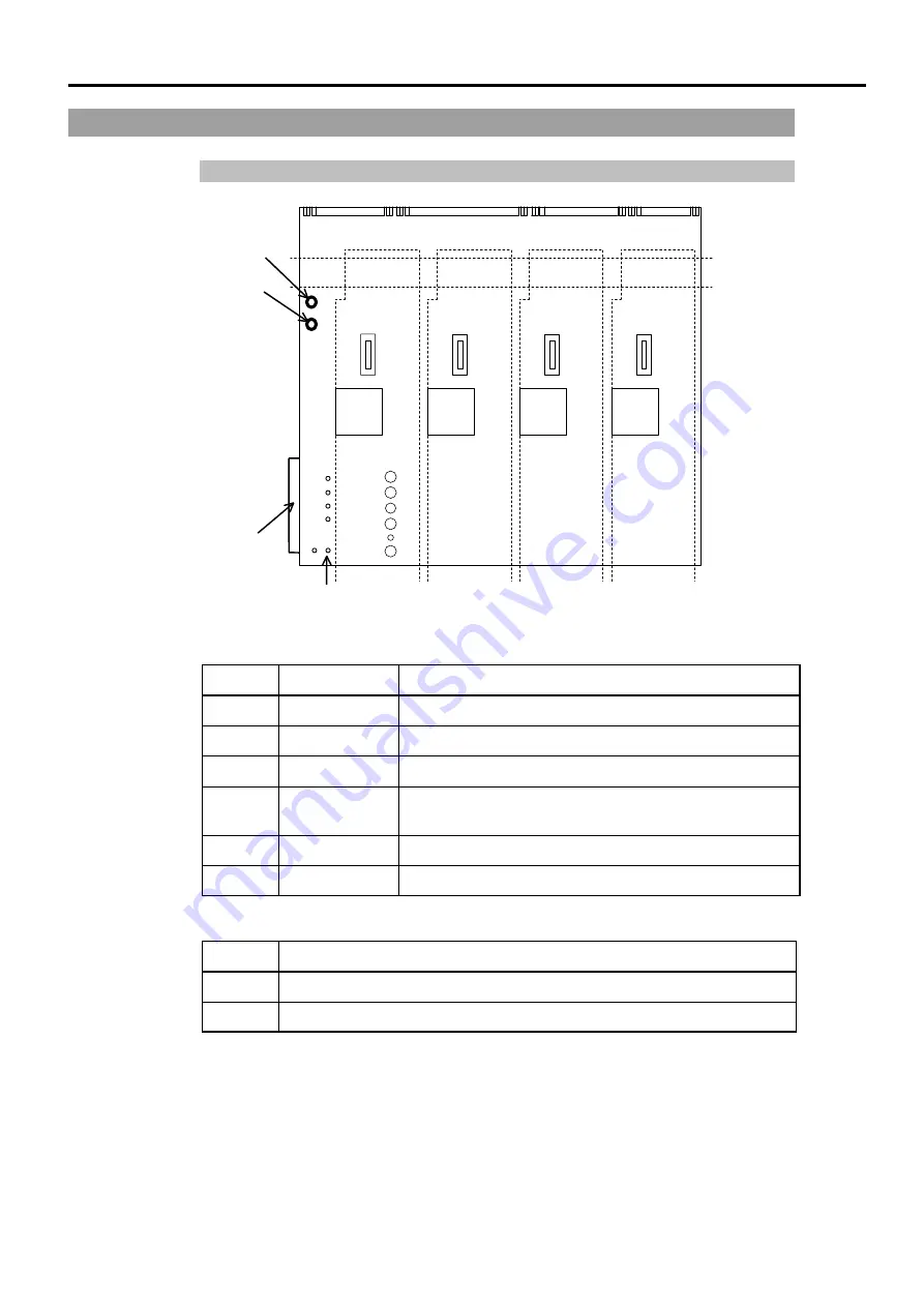
4.6.1 Layout and Functions
TP6
TP5
TP4
TP3
TP2
TP1
The through-holes (test pins) for voltage check
No. Through-hole
Description
TP1
+5V
+5V voltage for DMB
TP2
+5VA
+5V voltage for the Motor Driver module
TP3
−
5V
-
5V voltage for the Motor Driver module
TP4
+24V
+24V output voltage of the Switching Power Supply
module
TP5
+5.6V
Encoder power supply voltage
TP6
GND
GND for TP1 through TP5
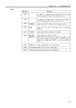
LED
No. Description
1
ON while the power for Encoder is output.
2
ON while the Manipulator’s electromagnetic brake is released.
CN5
CN6
CN7
CN8
LED2
LED1
CN11
The through-holes (test pins) for voltage check
Summary of Contents for SRC520
Page 1: ...SRC520 Rev 4 EM015C868F ROBOT CONTROLLER ...
Page 2: ...ROBOT CONTROLLER SRC520 Rev 4 ...
Page 13: ...Function The manual herein explains in detail the functions of the robot controller SRC520 ...
Page 14: ...Function 2 ...
Page 29: ...Function 2 3 Control Unit Part Names and Functions 17 2 3 4 Dimensions mm ...
Page 35: ...Function 2 4 Drive Unit Part Names and Functions 23 2 4 5 Dimensions mm ...
Page 36: ...Function 2 4 Drive Unit Part Names and Functions 24 ...
Page 50: ...Function 3 5 Noise Countermeasures Installation 38 ...
Page 66: ...Function 6 3 Pin Assignments D I O Connector 54 ...
Page 96: ...Function 9 2 Preparation for Communication RS 232C Settings 84 ...
Page 106: ...Function 11 Stand alone Option for SRC520 94 ...
Page 108: ...Maintenance 96 ...
Page 139: ...Maintenance 4 3 Drive Unit Drive Unit 127 4 3 Drive Unit 4 3 1 System Configuration ...


