Function 1. For Safety
4
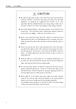
CAUTION
The power supply voltage switch on the Control Unit must be set and kept at
[230] side (AC200V to AC240V) when using the Control Unit with other
equipment. If connecting the equipment with AC200V (or the local
equivalent) under the condition that the power supply voltage switch is set at
[115] side (AC100V to AC120V), the equipment will be damaged seriously.
Only install optional hardware specifically designed for the SRC520 in the
Control Unit. Do not install any other software than originally installed in
the Control Unit at shipping. Otherwise, the warranty is void.
Check on the Connection Check Label, DU number (at Control Unit) and
Signature Labels (at Drive Unit & Manipulator) when connecting those units.
If those units are misconnected, the robot may not function properly or may be
damaged.
If there are more than one Drive Units connected to the Control Unit, make
sure that the DU numbers (DU1 - DU3) indicated at the Control Unit (above
the MIB connector) and the Drive Unit (above the MOTION connector)
match. It is highly dangerous if those do not match, causing to activate an
unintended robot.
Ensure all cables are securely connected. Avoid placing anything heavy on
the cables, and, do not bend them excessively, because this may damage the
cables, preventing the robot from functioning properly.
The AC power cable and the AC OUTLET connector on the Drive Unit are
directly connected inside the unit. Therefore, no matter if the Drive Unit is
ON or OFF, the AC OUTLET connector is constantly outputting AC200V (or
the local equivalent) power which requires extra caution.
When using I/O at the remote setup, always make sure before allowing
current to flow that the cable connection matches to the pin assignments.
Failure to do so may cause damage to/by the peripheral equipment.
At performance testing, prepare for some kind of failure with initial settings
or cable connection and, therefore, take extra caution.
Summary of Contents for SRC520
Page 1: ...SRC520 Rev 4 EM015C868F ROBOT CONTROLLER ...
Page 2: ...ROBOT CONTROLLER SRC520 Rev 4 ...
Page 13: ...Function The manual herein explains in detail the functions of the robot controller SRC520 ...
Page 14: ...Function 2 ...
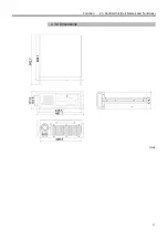
Page 29: ...Function 2 3 Control Unit Part Names and Functions 17 2 3 4 Dimensions mm ...
Page 35: ...Function 2 4 Drive Unit Part Names and Functions 23 2 4 5 Dimensions mm ...
Page 36: ...Function 2 4 Drive Unit Part Names and Functions 24 ...
Page 50: ...Function 3 5 Noise Countermeasures Installation 38 ...
Page 66: ...Function 6 3 Pin Assignments D I O Connector 54 ...
Page 96: ...Function 9 2 Preparation for Communication RS 232C Settings 84 ...
Page 106: ...Function 11 Stand alone Option for SRC520 94 ...
Page 108: ...Maintenance 96 ...
Page 139: ...Maintenance 4 3 Drive Unit Drive Unit 127 4 3 Drive Unit 4 3 1 System Configuration ...

