Maintenance 5. Check List for the Manipulator Operation
148
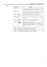
Control Unit – System Panel LED
From power-on to SPEL 95 launch
While running the SPEL 95
E-STOP
When the main power is turned ON, the light must turn ON momentarily and
must go OFF unless there is an emergency stop input.
If there is an emergency stop input at this time, the light must stay ON.
This lamp turns ON when there is an EMERGENCY STOP input to the Control
Unit’s OPTIONAL DEVICE connector and the Drive Unit’s EMERGENCY
connector.
RUN
The lamp must be blinking.
The lamp must be ON.
ERROR
The lamp must be blinking.
The lamp is OFF under normal
conditions.
It must turn ON when there is a system
error.
7 segment
When the main power is turned ON,
“8” lights up momentarily and goes
OFF.
The displayed data must change
from “0” in order to indicate the
system condition that is checked at
the beginning of SPEL 95 launch.
The lamp is OFF under normal
conditions.
In case of system error, it must display
the status of the error by the designated
number. (For details, refer to the
“Appendix B” in the SRC5**/SPEL 95
Appendix manual.)
(3) Execute MOTOR ON and check the followings:
・
No error displayed.
・
The MOTOR POWER LED on the Drive Unit’s Front Panel turns ON.
・
The Manipulator operates normally, and there is excitation.
(4) Execute various motion commands (such as JUMP, etc.). The robot must operate
accordingly and normally without vibration or abnormal sounds.
Summary of Contents for SRC520
Page 1: ...SRC520 Rev 4 EM015C868F ROBOT CONTROLLER ...
Page 2: ...ROBOT CONTROLLER SRC520 Rev 4 ...
Page 13: ...Function The manual herein explains in detail the functions of the robot controller SRC520 ...
Page 14: ...Function 2 ...
Page 29: ...Function 2 3 Control Unit Part Names and Functions 17 2 3 4 Dimensions mm ...
Page 35: ...Function 2 4 Drive Unit Part Names and Functions 23 2 4 5 Dimensions mm ...
Page 36: ...Function 2 4 Drive Unit Part Names and Functions 24 ...
Page 50: ...Function 3 5 Noise Countermeasures Installation 38 ...
Page 66: ...Function 6 3 Pin Assignments D I O Connector 54 ...
Page 96: ...Function 9 2 Preparation for Communication RS 232C Settings 84 ...
Page 106: ...Function 11 Stand alone Option for SRC520 94 ...
Page 108: ...Maintenance 96 ...
Page 139: ...Maintenance 4 3 Drive Unit Drive Unit 127 4 3 Drive Unit 4 3 1 System Configuration ...


