Function 2.2 Standard Specifications (Part Names and Functions)
9
2.2 Standard Specifications
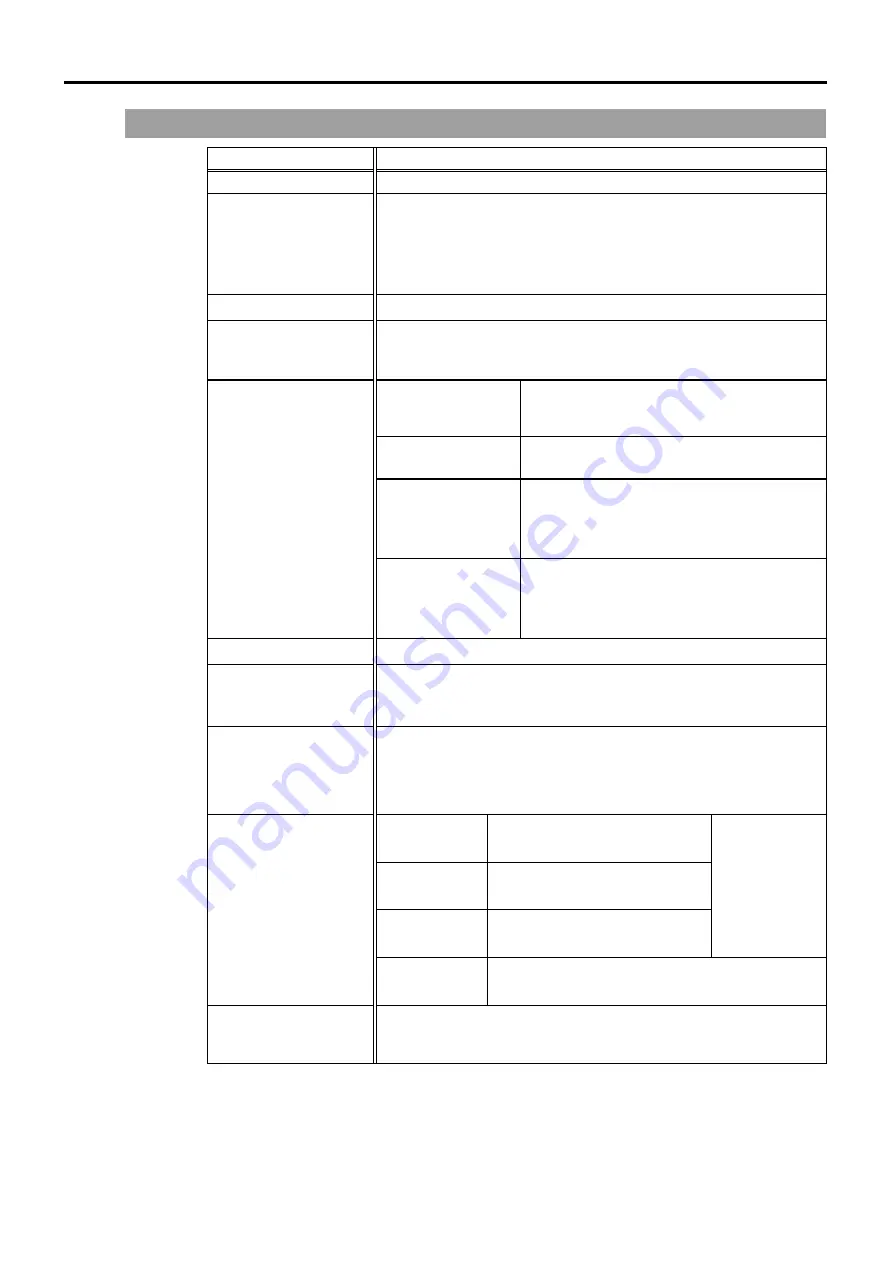
Item Specification
Model SRC520
Control Unit
PC compatible computer optimized for SRC520:
CPU
: Pentium 200MHz or faster
HD/RAM
: 1GB/32MB or more
OS
: Windows 95
Drive Unit
Up to four (4) connectable AC Servo Motors
Controllable Axes
Max. 16
(For the number of controlled axis, refer to the “Function 2.3.5
Control Unit Capability”.)
Programming
Language and Robot
Control Software
SPEL 95 (a multi-task robot language)
Joint Control
Simultaneous control over all the six (6) joints
Software AC servo control
Speed Control
PTP motion :
Programmable in the range of
1 to 100%
CP motion :
programmable (Actual value to
be manually entered.)
Robot
M
anipulator
Control
Acceleration/
Deceleration Control
PTP motion :
Programmable in the range of
1 to 100%; Automatic
CP motion :
programmable (Actual value to
be manually entered.)
Positioning Control
PTP (Pose-To-Pose control)/CP (Continuous Path control)
Memory Capacity
Programmable Area
: 2MB
Pose Data Area
:
Max. 2000 poses programmable
(per Manipulator)
Teaching Method
Remote
Direct
MDI (Manual Data Input)
Standard I/O
input :
16
output : 16
Extension I/O
input : 32 (per board)
output : 32 (per board)
Remote I/O
Up to 128 (per board) for both
input and output included
Remote
functions
allocable
External Input/ Output
Signals
Total I/O
input :
512
output : 512
Communication Interface
RS-232C (
×
2) (standard)
Ethernet (option)
Summary of Contents for SRC520
Page 1: ...SRC520 Rev 4 EM015C868F ROBOT CONTROLLER ...
Page 2: ...ROBOT CONTROLLER SRC520 Rev 4 ...
Page 13: ...Function The manual herein explains in detail the functions of the robot controller SRC520 ...
Page 14: ...Function 2 ...
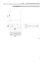
Page 29: ...Function 2 3 Control Unit Part Names and Functions 17 2 3 4 Dimensions mm ...
Page 35: ...Function 2 4 Drive Unit Part Names and Functions 23 2 4 5 Dimensions mm ...
Page 36: ...Function 2 4 Drive Unit Part Names and Functions 24 ...
Page 50: ...Function 3 5 Noise Countermeasures Installation 38 ...
Page 66: ...Function 6 3 Pin Assignments D I O Connector 54 ...
Page 96: ...Function 9 2 Preparation for Communication RS 232C Settings 84 ...
Page 106: ...Function 11 Stand alone Option for SRC520 94 ...
Page 108: ...Maintenance 96 ...
Page 139: ...Maintenance 4 3 Drive Unit Drive Unit 127 4 3 Drive Unit 4 3 1 System Configuration ...


