Function 2.2 Standard Specifications (Part Names and Functions)
10
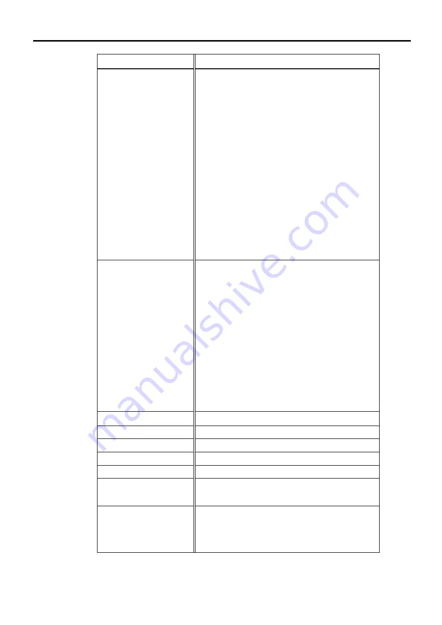
Item Specification
Safety Features
- Emergency stop switch
- Safety door input
- Low power mode
- Dynamic brake
- Encoder cable disconnection error detection
- Motor overload detection
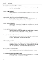
- Irregular motor torque (out-of-control Manipulator)
detection
- Motor speed error detection
- Positioning overflow - servo error - detection
- Speed overflow - servo error - detection
- CPU irregularity detection
- Memory check-sum error detection
- Overheat detection at the Motor Drive Module
- Safety key lock on the JP500/OP500 for mode switch
(NORMAL/ATTEND).
Option
- Extension I/O Board (Input: 32 Output: 32
/ A special optional cable is prepared.)
- Pulse Generating Board (4 additional controllable
axes/one board / A special optional cable is
prepared.)
- Remote I/O Board (Input and Output total: 128)
- Ethernet Board
- Vision Option
- Multi-Manipulator Option
- Custom Manipulator Option
- Conveyor Tracking Option
- Jog Pad, JP500
- Operation Pendant, OP500
Power Source
AC 200V to AC 240V / S
ingle phase
50/60Hz *
Power Consumption
Max. 2000W (Depending on the manipulator model)
*
Insulation Resistance
100M
Ω
or more
Rated Ambient Temperature
5 to 40
°
C
Rated Relative Humidity
10 to 80 %
Weight
Control Unit
:18
kg
Drive Unit
:14
kg
Size
For the Control Unit,
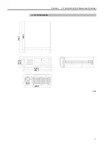
refer to the “Function 2.3.4 Dimensions”.
For the Drive Unit,
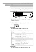
refer to the “Function 2.4.5 Dimensions”.
* When only using the Control Unit, the specification is different.
Refer to the “Function 11. Stand-alone Option for SRC520”.
Summary of Contents for SRC520
Page 1: ...SRC520 Rev 4 EM015C868F ROBOT CONTROLLER ...
Page 2: ...ROBOT CONTROLLER SRC520 Rev 4 ...
Page 13: ...Function The manual herein explains in detail the functions of the robot controller SRC520 ...
Page 14: ...Function 2 ...
Page 29: ...Function 2 3 Control Unit Part Names and Functions 17 2 3 4 Dimensions mm ...
Page 35: ...Function 2 4 Drive Unit Part Names and Functions 23 2 4 5 Dimensions mm ...
Page 36: ...Function 2 4 Drive Unit Part Names and Functions 24 ...
Page 50: ...Function 3 5 Noise Countermeasures Installation 38 ...
Page 66: ...Function 6 3 Pin Assignments D I O Connector 54 ...
Page 96: ...Function 9 2 Preparation for Communication RS 232C Settings 84 ...
Page 106: ...Function 11 Stand alone Option for SRC520 94 ...
Page 108: ...Maintenance 96 ...
Page 139: ...Maintenance 4 3 Drive Unit Drive Unit 127 4 3 Drive Unit 4 3 1 System Configuration ...


