Function 2.3 Control Unit (Part Names and Functions)
14
(7)
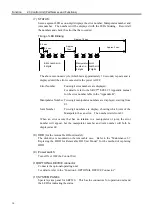
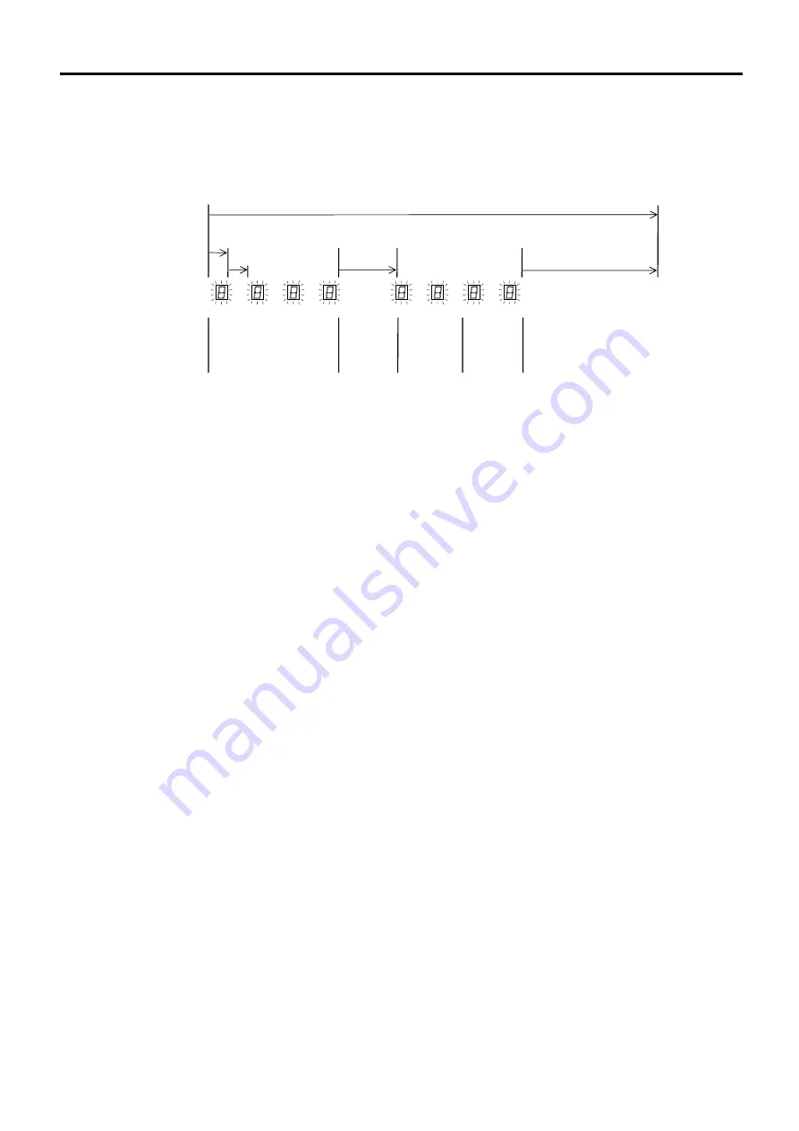
STATUS:
Seven-segment LED as one-digit displays the error number, Manipulator number and
joint number. The numbers will be displayed with the LEDs blinking. Record all
the numbers and check the error that has occurred.
Timing of LED Blinking
Approx. 3 sec.
Approx. 10 sec.
Approx.
0.4 sec.
0.4 sec.
Joint
number in
2 digits
Manipulator
number in
2 digits
Error number in
4 digits
1 sec.
The above mentioned cycle (which lasts approximately 10 seconds) repeats and is
displayed until the error is canceled or the power is OFF.
Error Number
: Four-digit error numbers are displayed.
For details, refer to the SRC5**/SPEL 95 Appendix manual
for the error number table in the “Appendix B”.
Manipulator Number : Two-digit manipulator numbers are displayed, starting from
01.
Joint Number
: Two-digit numbers are display, showing which joint of the
Manipulator has an error. The number starts from 01.
When an error occurs that has no relation to a manipulator or joint, the error
number will appear, but the manipulator number and joint number will both be
displayed as 00.
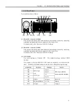
(8) HDD (
for the removable HD unit model):
The disk drive is mounted on the removable case. Refer to the “Maintenance 3.7
Replacing the HDD for Removable HD Unit Model” for the method of replacing
HDD.
(9) Power switch:
Turns ON or OFF the Control Unit.
(10) OPTIONAL DEVICE connector:
Connects the optional operating unit.
For details, refer to the “Function 4. OPTIONAL DEVICE Connector”.
(11) SYSTEM PANEL
:
Special system panel for SRC520. This has the connectors for operation units and
the LED for indicating the status.
Summary of Contents for SRC520
Page 1: ...SRC520 Rev 4 EM015C868F ROBOT CONTROLLER ...
Page 2: ...ROBOT CONTROLLER SRC520 Rev 4 ...
Page 13: ...Function The manual herein explains in detail the functions of the robot controller SRC520 ...
Page 14: ...Function 2 ...
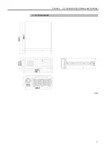
Page 29: ...Function 2 3 Control Unit Part Names and Functions 17 2 3 4 Dimensions mm ...
Page 35: ...Function 2 4 Drive Unit Part Names and Functions 23 2 4 5 Dimensions mm ...
Page 36: ...Function 2 4 Drive Unit Part Names and Functions 24 ...
Page 50: ...Function 3 5 Noise Countermeasures Installation 38 ...
Page 66: ...Function 6 3 Pin Assignments D I O Connector 54 ...
Page 96: ...Function 9 2 Preparation for Communication RS 232C Settings 84 ...
Page 106: ...Function 11 Stand alone Option for SRC520 94 ...
Page 108: ...Maintenance 96 ...
Page 139: ...Maintenance 4 3 Drive Unit Drive Unit 127 4 3 Drive Unit 4 3 1 System Configuration ...

