Function 3.4 Cable Connection (Installation)
35
3.4.3 Connecting a Drive Unit to the Manipulator
Connect a Drive Unit to the Manipulator by using M/C Power cable and M/C Signal
cable.
M/C power cable :
M/C Power cable has round connectors with 17-pins on both ends.
Connect the female connector to the POWER connector at the
Manipulator and the male connector to the M/C POWER
connector at the Drive Unit. Insert the connectors and rotate
clockwise until you hear a “click”.
M/C Signal cable :
M/C Signal cable has square connectors with 68-pins on both ends.
Connect the signal cable to the SIGNAL connector at the
Manipulator and the M/C SIGNAL connector at the Drive Unit.
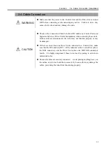
WARNING
Make sure that the power to the Control Unit and the Drive Unit is turned OFF
before connecting or disconnecting any cables. Failure to do so may cause
electric shock and may damage the units.
CAUTION
Check on the Connection Check Label, DU number (at Control Unit) and
Signature Labels (at Drive Unit & Manipulator) when connecting those units.
If those units are misconnected, the robot may not function properly or may be
damaged.
Ensure all cables are securely connected. Avoid placing anything heavy on the
cables, and, do not bend them excessively, because this may damage the cables,
preventing the robot from functioning properly.
The setting data for the manipulator and manipulator model are stored in the Control Unit.
Therefore, it is crucial that the manipulator has to be itself specified on the Connection
Check label on the front panel of the Control Unit (see previous figures) be connected.
You may also find the proper Manipulator’s serial No. on your left hand side facing the
Drive Unit.
MANIPULATOR
00002
ES551S
Manipulator serial number
Manipulator model
The Manipulator’s serial No. is indicated on the signature label on the back of the
Manipulator.
)
NOTE
Summary of Contents for SRC520
Page 1: ...SRC520 Rev 4 EM015C868F ROBOT CONTROLLER ...
Page 2: ...ROBOT CONTROLLER SRC520 Rev 4 ...
Page 13: ...Function The manual herein explains in detail the functions of the robot controller SRC520 ...
Page 14: ...Function 2 ...
Page 29: ...Function 2 3 Control Unit Part Names and Functions 17 2 3 4 Dimensions mm ...
Page 35: ...Function 2 4 Drive Unit Part Names and Functions 23 2 4 5 Dimensions mm ...
Page 36: ...Function 2 4 Drive Unit Part Names and Functions 24 ...
Page 50: ...Function 3 5 Noise Countermeasures Installation 38 ...
Page 66: ...Function 6 3 Pin Assignments D I O Connector 54 ...
Page 96: ...Function 9 2 Preparation for Communication RS 232C Settings 84 ...
Page 106: ...Function 11 Stand alone Option for SRC520 94 ...
Page 108: ...Maintenance 96 ...
Page 139: ...Maintenance 4 3 Drive Unit Drive Unit 127 4 3 Drive Unit 4 3 1 System Configuration ...


