Function 3.5 Noise Countermeasures (Installation)
36
3.5 Noise Countermeasures
The followings must be observed in the system’s cable wiring:
・
The earth wire of the power supply should be grounded. (Ground resistance: less than
100
Ω
)
It is important to ground the frame of Drive Unit not only for prevention from electric
shock, but also for reducing the influence of electric noise around the Drive Unit.
Therefore, be sure to connect the earth wire (yellow/green) of the Drive Unit’s power
cable to the ground terminal of the factory power supply. For details about the plug
and AC power cable, refer to the “Function 3.3.2 Power Plug”.
・
Do not tap power from a power line that connects to any equipment which may cause
noise.
・
When you tap power for the controller and the single-phase AC motor from the same
power line, change the phase of one of the other. Ensure that they will not be the
same phase.
・
Use a twisted pair motor power line.
・
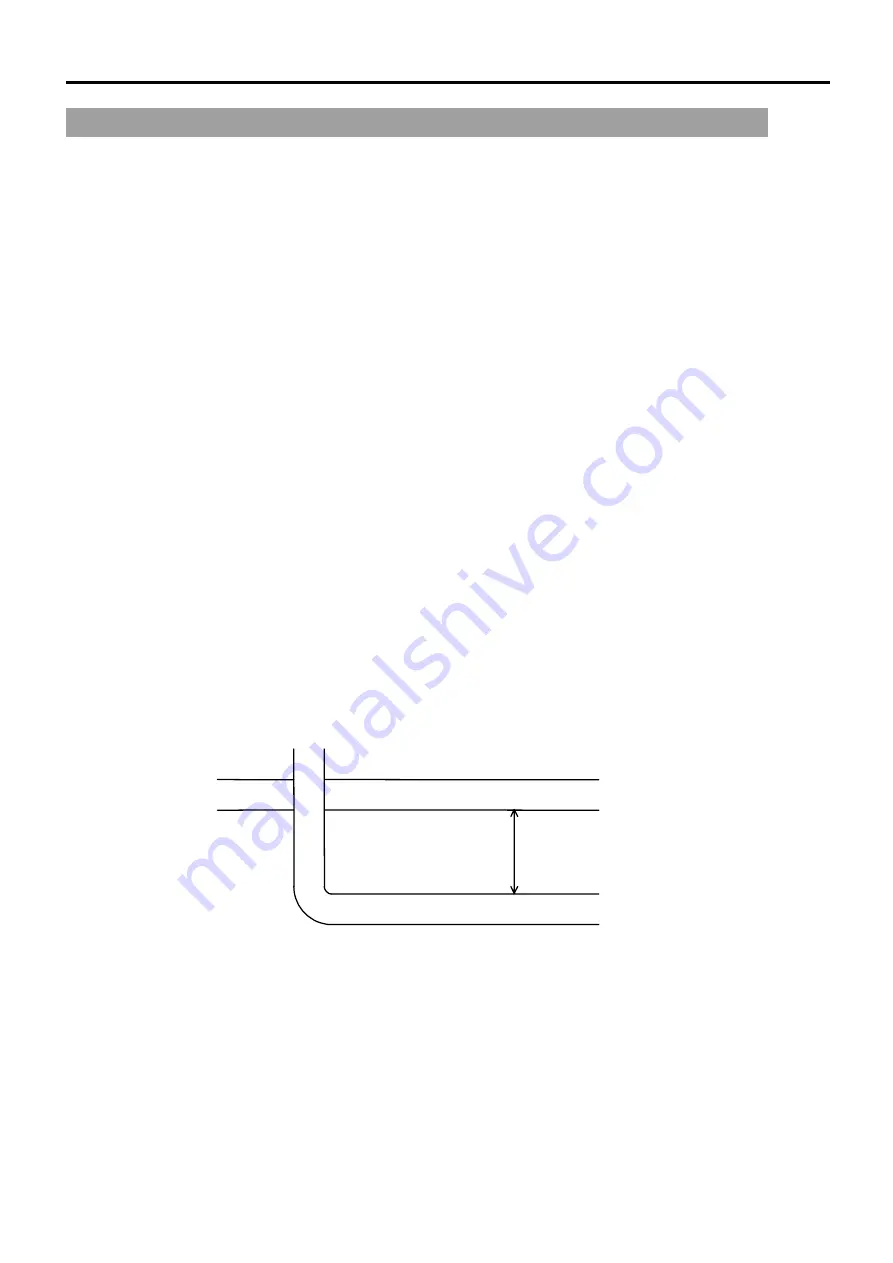
Do not run AC power lines and DC power lines in the same wiring duct, and separate
them by at least 200 mm. For example, separate the AC motor power line and the
controller power line by at least 200 mm from the sensor or valve I/O lines; and do not
bundle both sets of wiring with the same cable tie. If more than one duct/cable must
cross each other, they should cross perpendicularly. The preferable example is
shown below:
AC Line duct
DC line duct
200 mm or more
・
For I/O lines, wire it as short as possible and use a shielded wire and clamp the shield
to the attached I/O connector interior.
・
Use a shielded wire for the EMERGENCY connector and clamp the shield to the
interior of the connector.
Summary of Contents for SRC520
Page 1: ...SRC520 Rev 4 EM015C868F ROBOT CONTROLLER ...
Page 2: ...ROBOT CONTROLLER SRC520 Rev 4 ...
Page 13: ...Function The manual herein explains in detail the functions of the robot controller SRC520 ...
Page 14: ...Function 2 ...
Page 29: ...Function 2 3 Control Unit Part Names and Functions 17 2 3 4 Dimensions mm ...
Page 35: ...Function 2 4 Drive Unit Part Names and Functions 23 2 4 5 Dimensions mm ...
Page 36: ...Function 2 4 Drive Unit Part Names and Functions 24 ...
Page 50: ...Function 3 5 Noise Countermeasures Installation 38 ...
Page 66: ...Function 6 3 Pin Assignments D I O Connector 54 ...
Page 96: ...Function 9 2 Preparation for Communication RS 232C Settings 84 ...
Page 106: ...Function 11 Stand alone Option for SRC520 94 ...
Page 108: ...Maintenance 96 ...
Page 139: ...Maintenance 4 3 Drive Unit Drive Unit 127 4 3 Drive Unit 4 3 1 System Configuration ...


