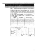
Function 5.2 Emergency Stop Switch (EMERGENCY connector)
43
5.2 Emergency Stop Switch
WARNING
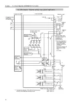
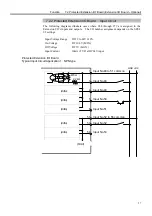
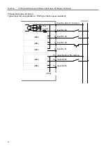
Do refer to the typical application diagram in the “Function 5.4 Circuit
Diagrams” when wiring to the EMERGENCY connector so that it should not
dysfunction the emergency stop input at the Control Unit via the OPTIONAL
DEVICE connector.
5.2.1 Emergency Stop Switch
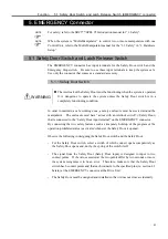
If it is desired to create an external Emergency Stop switch(es) in addition to the
Emergency Stop that an operation unit (JP500/OP500) provides, make sure to connect
such Emergency Stop switch(es) to the proper pins at the EMERGENCY connector.
The Emergency Stop switch connected must comply with the following:
- It must be a push button switch that is “normally closed.”
- A button that does not automatically return or resume.
- The button must be mushroom-shaped and red.
- The button must have a double contact that is “normally closed.”
The signal from the Emergency Stop switch is designed to input with two circuits.
If the values entered at the two circuits differ by two seconds or more, the system
recognizes it as an error. Therefore, make sure that the Emergency Stop switch has a
double contact and that each connects to the specified pins at the EMERGENCY
connector at the Drive Unit. Refer to the “Function 5.4 Circuit Diagrams”.
5.2.2 Checking the Functions of Emergency Stop Switch
Once the Emergency Stop switch is connected to the EMERGENCY connector, continue
the following procedure to make sure that the switch functions properly. For the safety
of the operator, the robot must not be powered ON until the following test is completed.
(1) Turn ON the Control Unit and the Drive Unit to launch the SPEL 95 while pressing
the Emergency Stop switch.
(2) Make sure that both the “E-STOP” LEDs on the Control Unit’s system panel and the
Drive Unit’s front panel are ON.
(3) Make sure that “Emergency Stop” is displayed on the status bar on the monitor
window.
(4) Release the Emergency Stop Switch.
(5) Execute RESET command.
(6) Make sure that “E-STOP” LED is turned OFF and the “Emergency Stop” is
disappeared from the status bar.
For the emergency condition to be related timely to the peripheral equipment at the input
of the Emergency Stop at Drive Unit via the EMERGENCY connector, make sure that
the desired equipment be connected to the Emergency Stop output terminals. The relay
contacts at the EMERGENCY connector (#5 & #6) (normally closed) will open at the
input of Emergency Stop state.
)
NOTE
)
NOTE
Summary of Contents for SRC520
Page 1: ...SRC520 Rev 4 EM015C868F ROBOT CONTROLLER ...
Page 2: ...ROBOT CONTROLLER SRC520 Rev 4 ...
Page 13: ...Function The manual herein explains in detail the functions of the robot controller SRC520 ...
Page 14: ...Function 2 ...
Page 29: ...Function 2 3 Control Unit Part Names and Functions 17 2 3 4 Dimensions mm ...
Page 35: ...Function 2 4 Drive Unit Part Names and Functions 23 2 4 5 Dimensions mm ...
Page 36: ...Function 2 4 Drive Unit Part Names and Functions 24 ...
Page 50: ...Function 3 5 Noise Countermeasures Installation 38 ...
Page 66: ...Function 6 3 Pin Assignments D I O Connector 54 ...
Page 96: ...Function 9 2 Preparation for Communication RS 232C Settings 84 ...
Page 106: ...Function 11 Stand alone Option for SRC520 94 ...
Page 108: ...Maintenance 96 ...
Page 139: ...Maintenance 4 3 Drive Unit Drive Unit 127 4 3 Drive Unit 4 3 1 System Configuration ...

