Function 5.3 Pin Assignments (EMERGENCY connector)
44
5.3 Pin Assignments
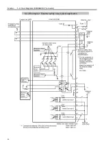
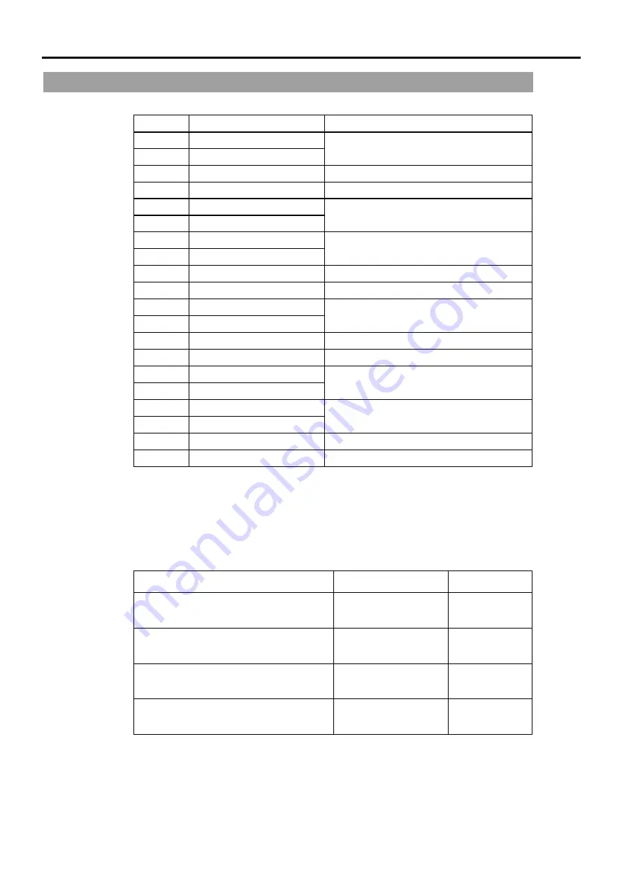
The EMERGENCY connector pin assignments are as follows:
Pin No.
Signal
Function
1 E_SW11
2 E_SW12
Emergency Stop switch output (1)
3
E.STOP1+
Emergency Stop input 1 (+)
4
E.STOP1
-
Emergency Stop input 1 (
-
)
5 E.STOP
OUT
6 E.STOP
OUT
Emergency Stop condition output
(Relay contact)
*1
7 GUARD11
8 GUARD12
Safety Door input (1)
*2
9 +24V
+24V
output
10
+24VGND
+24V GND output
11 E_SW21
12 E_SW22
Emergency Stop switch output (2)
13
E.STOP2+
Emergency Stop input 2 (+)
14
E.STOP2
-
Emergency Stop input 2 (
-
)
15 RELEACE
16 RELEACE
Latch Release input
17 GUARD21
18 GUARD22
Safety Door input (2)
*2
19 +24V
+24V
output
20
+24VGND
+24V GND output
*1 The Emergency Stop condition is output via relay contact when it is open (it is
normally closed).
*2 It becomes an error if the input values from the Safety Door 1 and Safety Door 2 are
apart by two or more seconds. They must be connected to the same switch with
two contacts.
Emergency Stop switch output rated load
DC30V 1A or under
1-2, 11-12 pin
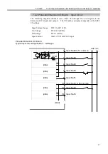
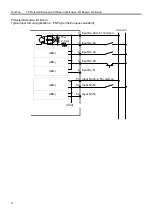
Emergency Stop rated input voltage range
Emergency Stop rated input current
DC24V
±
10%
10mA/24V input
3-4, 13-14 pin
Safety Door rated input voltage range
Safety Door rated input current
DC12 to 24V
±
10%
10mA/24V input
7-8, 17-18 pin
Latch Release rated input voltage range
Latch Release rated input current
DC12 to 24V
±
10%
10mA/24V input
15-16 pin
Emergency Stop output relay contact rated
load
DC30V 0.5A or under
5-6 pin
The total electrical resistance of the Emergency Stop switches and their circuit should be
1
Ω
or less.
)
NOTE
Summary of Contents for SRC520
Page 1: ...SRC520 Rev 4 EM015C868F ROBOT CONTROLLER ...
Page 2: ...ROBOT CONTROLLER SRC520 Rev 4 ...
Page 13: ...Function The manual herein explains in detail the functions of the robot controller SRC520 ...
Page 14: ...Function 2 ...
Page 29: ...Function 2 3 Control Unit Part Names and Functions 17 2 3 4 Dimensions mm ...
Page 35: ...Function 2 4 Drive Unit Part Names and Functions 23 2 4 5 Dimensions mm ...
Page 36: ...Function 2 4 Drive Unit Part Names and Functions 24 ...
Page 50: ...Function 3 5 Noise Countermeasures Installation 38 ...
Page 66: ...Function 6 3 Pin Assignments D I O Connector 54 ...
Page 96: ...Function 9 2 Preparation for Communication RS 232C Settings 84 ...
Page 106: ...Function 11 Stand alone Option for SRC520 94 ...
Page 108: ...Maintenance 96 ...
Page 139: ...Maintenance 4 3 Drive Unit Drive Unit 127 4 3 Drive Unit 4 3 1 System Configuration ...


