iv
Safety Precautions
Please carefully read this manual and any other manuals before installing this robot system
(and definitely before connecting cables). Keep this manual in a handy location for easy
access at all times.
This sign indicates that a danger of serious injury or
death will exist if the instructions thereunder are not
followed.
This sign indicates that ignoring the instructions there-
under may cause harm to people or physical damage to
equipment and facilities.
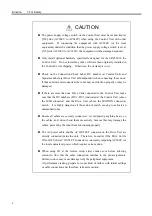
The manufacturer/supplier must design and construct this robot system in
accordance with the principles described in the “Safety” section of the
SRC5**/SPEL 95 Introduction Manual. Please read the Introduction Man-
ual first to follow Safety Precautions therein.
This robot has been designed and manufactured strictly for use in a normal
indoor environment. Do not use the robot in an environment that exceeds
the conditions set forth in the manuals for the manipulator and controller.
Do not use the robot outside of the usage conditions and product specifica-
tions described in the manuals. Doing so will not only adversely affect the
life of the product, but may also present a serious safety problem.
Only trained personnel should be allowed to design, install, operate, perform
function testing, and maintain this robot and the robot system. Trained per-
sonnel are those who have taken a robot training course (held by the dealer
on a regular basis) or those who have carefully read the manuals and have
equivalent knowledge or skill.
WARNING
CAUTION
WARNING
Summary of Contents for SRC520
Page 1: ...SRC520 Rev 4 EM015C868F ROBOT CONTROLLER ...
Page 2: ...ROBOT CONTROLLER SRC520 Rev 4 ...
Page 13: ...Function The manual herein explains in detail the functions of the robot controller SRC520 ...
Page 14: ...Function 2 ...
Page 29: ...Function 2 3 Control Unit Part Names and Functions 17 2 3 4 Dimensions mm ...
Page 35: ...Function 2 4 Drive Unit Part Names and Functions 23 2 4 5 Dimensions mm ...
Page 36: ...Function 2 4 Drive Unit Part Names and Functions 24 ...
Page 50: ...Function 3 5 Noise Countermeasures Installation 38 ...
Page 66: ...Function 6 3 Pin Assignments D I O Connector 54 ...
Page 96: ...Function 9 2 Preparation for Communication RS 232C Settings 84 ...
Page 106: ...Function 11 Stand alone Option for SRC520 94 ...
Page 108: ...Maintenance 96 ...
Page 139: ...Maintenance 4 3 Drive Unit Drive Unit 127 4 3 Drive Unit 4 3 1 System Configuration ...

