Function 7.2 Protected Extension I/O Board (Extension I/O Board – Optional)
59
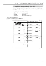
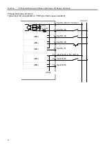
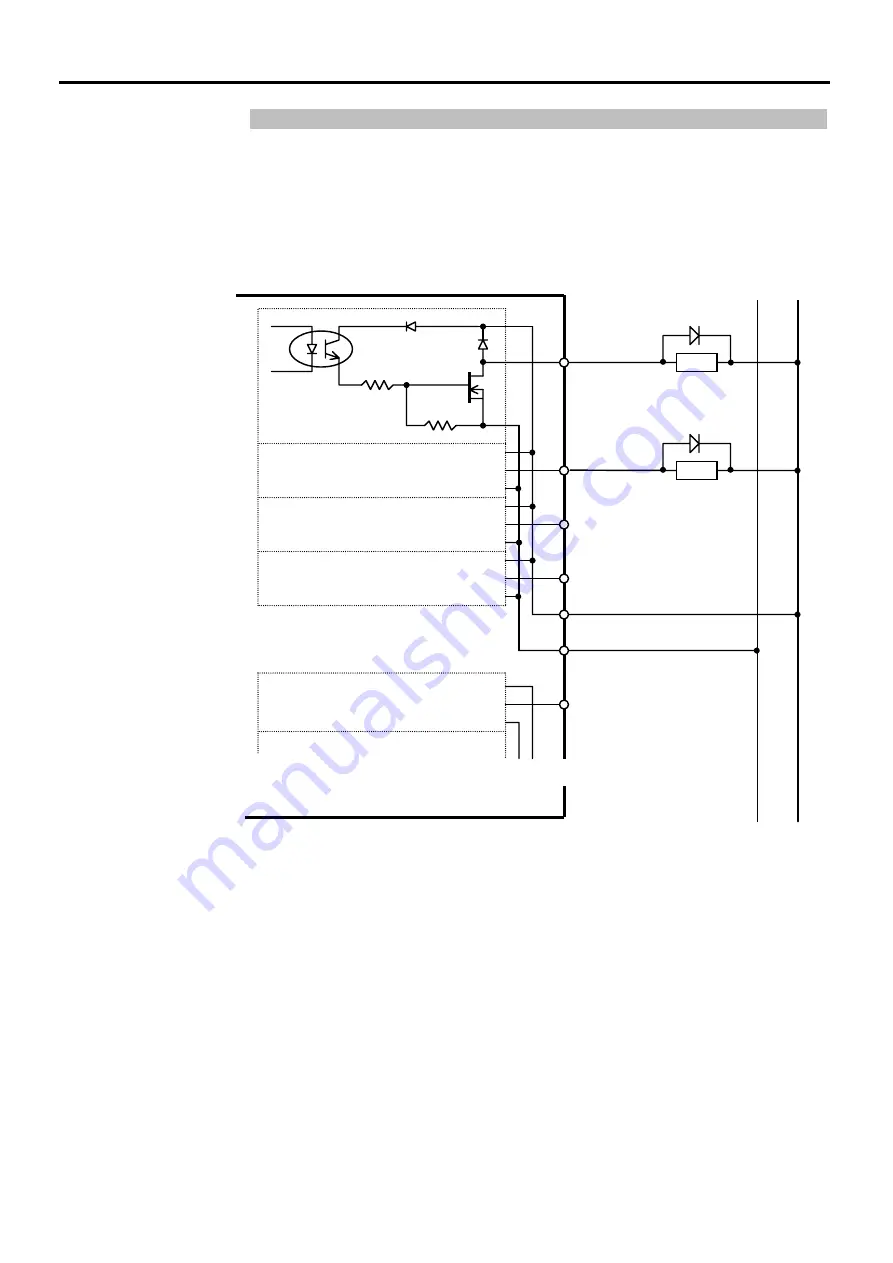
7.2.3 Protected Extension I/O Board : Output Circuit
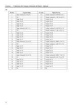
The following diagrams illustrate cases where #48 through #79 are assigned to the
Extension I/O’s inputs and outputs. The I/O number assignment depends on the SPEL
95 settings.
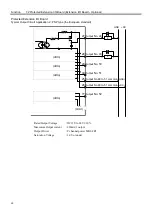
Protected Extension I/O Board
Typical Output Circuit Application 1 : NPN type
(ditto)
(ditto)
(ditto)
(ditto)
27
Output
No. 48
28
Output
No. 49
29
Output
No. 50
30
Output
No. 51
77
Output
No. 52
25
Output
No.48 to 51 common
(+DC)
26
Output No.48 to 51 common
(GND)
L
L
GND +DC
(Omit)
〜
〜
〜
~
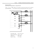
Rated Output Voltage
: DC12V to 24V
±
10%
Maximum Output current : 250mA/1 output
Output Driver
: N channel power MOS FET
Saturation Voltage
: 1.0V or under
Summary of Contents for SRC520
Page 1: ...SRC520 Rev 4 EM015C868F ROBOT CONTROLLER ...
Page 2: ...ROBOT CONTROLLER SRC520 Rev 4 ...
Page 13: ...Function The manual herein explains in detail the functions of the robot controller SRC520 ...
Page 14: ...Function 2 ...
Page 29: ...Function 2 3 Control Unit Part Names and Functions 17 2 3 4 Dimensions mm ...
Page 35: ...Function 2 4 Drive Unit Part Names and Functions 23 2 4 5 Dimensions mm ...
Page 36: ...Function 2 4 Drive Unit Part Names and Functions 24 ...
Page 50: ...Function 3 5 Noise Countermeasures Installation 38 ...
Page 66: ...Function 6 3 Pin Assignments D I O Connector 54 ...
Page 96: ...Function 9 2 Preparation for Communication RS 232C Settings 84 ...
Page 106: ...Function 11 Stand alone Option for SRC520 94 ...
Page 108: ...Maintenance 96 ...
Page 139: ...Maintenance 4 3 Drive Unit Drive Unit 127 4 3 Drive Unit 4 3 1 System Configuration ...


