Function 7.3 Extension I/O Board (Extension I/O Board – Optional)
62
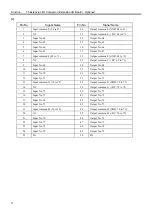
7.3.2 Extension I/O Board : Input Circuit
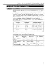
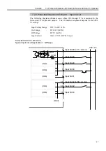
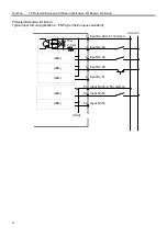
The input circuit is the same as the NPN type of the protected extension I/O board.
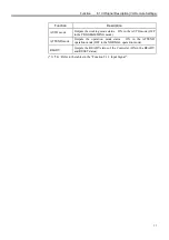
Refer to the “Function 7.2.2 Protected Extension I/O board : Input Circuit” for details.
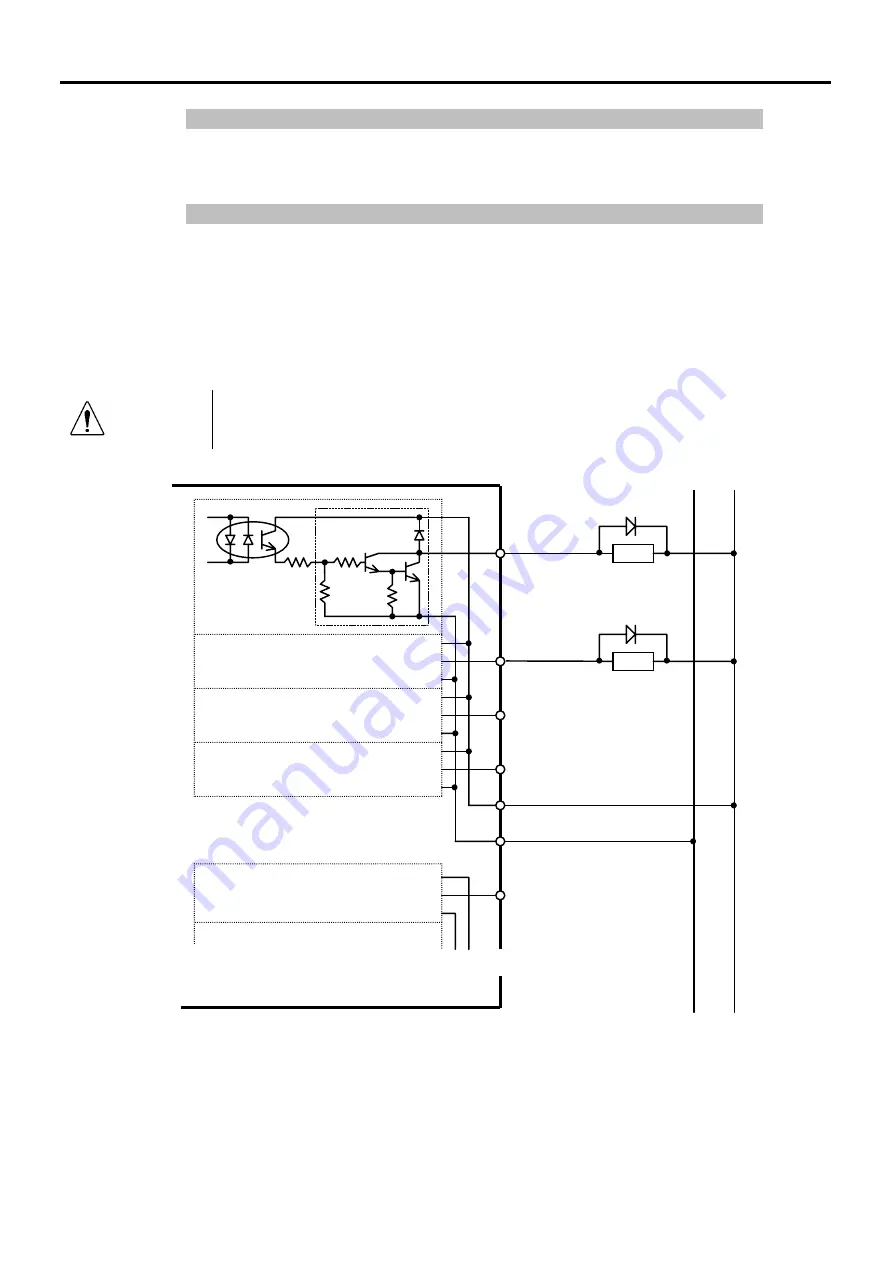
7.3.3 Extension I/O Board : Output Circuit
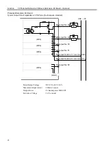
The following diagrams illustrate cases where #48 through #55 are assigned to the
Extension I/O’s inputs and outputs. The I/O number assignment depends on the SPEL
95 settings.
Extension I/O Board
I/O Typical Output Circuit Application 1 : Output #48 to #55 (Eight low numbers among thirty-two bit
numbers existing in one board are output.)
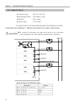
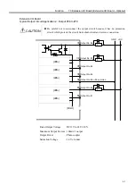
CAUTION
Be careful not to misconnect the output circuit because it has no protection
circuit which protects the circuit from short-circuit and reverse-connection.
(ditto)
(ditto)
(ditto)
(ditto)
27
Output No. 48
28
Output No. 4
9
29
Output No.
50
30
Output No.
51
77
Output No.
52
25
Output No. 48 to 51
common (+DC)
26
Output No.
48 to 51
common
(GND)
L
L
GND +DC
(Omit)
~
~
~
~
Transistor array
Rated Output Voltage
: DC12V to 24V
±
10%
Maximum Output current : 250mA/1 output
Output Driver
: Transistor array
Saturation Voltage
: 1.6V or under
Summary of Contents for SRC520
Page 1: ...SRC520 Rev 4 EM015C868F ROBOT CONTROLLER ...
Page 2: ...ROBOT CONTROLLER SRC520 Rev 4 ...
Page 13: ...Function The manual herein explains in detail the functions of the robot controller SRC520 ...
Page 14: ...Function 2 ...
Page 29: ...Function 2 3 Control Unit Part Names and Functions 17 2 3 4 Dimensions mm ...
Page 35: ...Function 2 4 Drive Unit Part Names and Functions 23 2 4 5 Dimensions mm ...
Page 36: ...Function 2 4 Drive Unit Part Names and Functions 24 ...
Page 50: ...Function 3 5 Noise Countermeasures Installation 38 ...
Page 66: ...Function 6 3 Pin Assignments D I O Connector 54 ...
Page 96: ...Function 9 2 Preparation for Communication RS 232C Settings 84 ...
Page 106: ...Function 11 Stand alone Option for SRC520 94 ...
Page 108: ...Maintenance 96 ...
Page 139: ...Maintenance 4 3 Drive Unit Drive Unit 127 4 3 Drive Unit 4 3 1 System Configuration ...


