Function 8.2 Timing Specifications (I/O Remote Settings)
78
8.2 Timing Specifications
8.2.1 Design Notes for Input Signal
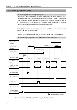
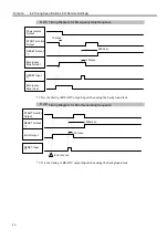
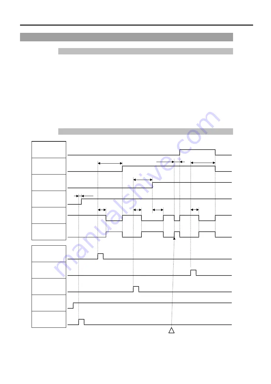
The following charts indicate timing sequence of the primary operations of the SRC520.
The indicated lapse (time duration) should be referred to only as reference value since the
actual timing value varies depending on the number of manipulators and running tasks as
well as CPU speed of the control unit PC. Check carefully and refer to the following
charts for the timing interrelation when you enter an input signal.
In designing, avoid simultaneous entries as much as possible to prevent errors since the
remote signal value is entered in pulse.
The pulse width of an input signal must be 10 or more millisecond to avoid chattering.
8.2.2 Timing Diagram for Operation Execution Sequence
Power status
Output
HOME Output
Mnp. No. output
Motor ON Input
Motor OFF Input
HOME Input
Mnp. No. Input
Sel. Mnp. Input
(confirm Mnp.No.)
1sec.
1sec.
HOME operation
10msec.
RESET Output
*1
START monitor
Output
Motor status
Output
POWER HIGH command
100msec.
50msec. 150msec.
10msec.
100msec.
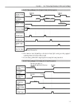
*1: It is the timing of READY output when using the background task.
Summary of Contents for SRC520
Page 1: ...SRC520 Rev 4 EM015C868F ROBOT CONTROLLER ...
Page 2: ...ROBOT CONTROLLER SRC520 Rev 4 ...
Page 13: ...Function The manual herein explains in detail the functions of the robot controller SRC520 ...
Page 14: ...Function 2 ...
Page 29: ...Function 2 3 Control Unit Part Names and Functions 17 2 3 4 Dimensions mm ...
Page 35: ...Function 2 4 Drive Unit Part Names and Functions 23 2 4 5 Dimensions mm ...
Page 36: ...Function 2 4 Drive Unit Part Names and Functions 24 ...
Page 50: ...Function 3 5 Noise Countermeasures Installation 38 ...
Page 66: ...Function 6 3 Pin Assignments D I O Connector 54 ...
Page 96: ...Function 9 2 Preparation for Communication RS 232C Settings 84 ...
Page 106: ...Function 11 Stand alone Option for SRC520 94 ...
Page 108: ...Maintenance 96 ...
Page 139: ...Maintenance 4 3 Drive Unit Drive Unit 127 4 3 Drive Unit 4 3 1 System Configuration ...


