Function 9.1 RS-232C cable (RS-232C Settings)
81
9.
RS-232C Settings
The Standard Control Unit comes with two RS-232C channels to facilitate controlling of
the data communication among the host computer, robots and their peripheral equipment.
9.1 RS-232C cable
The RS-232C cable is not included in the standard SRC520 model. Prepare them as
necessary.
The cable must be twisted shield pair. Clamp the shield on the hood to prevent noise.
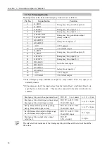
9.1.1 Pin Assignments
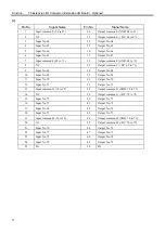
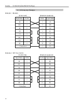
Pin assignments for RS-232C connector are as follows:
Pin No.
(Abbr.) Signal Name
Signal Direction
1
CD
Data carrier detect
Input
2 RD
Receive
data
Input
3 SD
Send
data
Output
4 ER
Terminal
ready
Output
5 SG
Signal
ground
-
6
DR
Data set ready
Input
7
RS
Request to send
Output
8
CS
Clear to send
Input
9 RI
Ring
indicator
Input
Summary of Contents for SRC520
Page 1: ...SRC520 Rev 4 EM015C868F ROBOT CONTROLLER ...
Page 2: ...ROBOT CONTROLLER SRC520 Rev 4 ...
Page 13: ...Function The manual herein explains in detail the functions of the robot controller SRC520 ...
Page 14: ...Function 2 ...
Page 29: ...Function 2 3 Control Unit Part Names and Functions 17 2 3 4 Dimensions mm ...
Page 35: ...Function 2 4 Drive Unit Part Names and Functions 23 2 4 5 Dimensions mm ...
Page 36: ...Function 2 4 Drive Unit Part Names and Functions 24 ...
Page 50: ...Function 3 5 Noise Countermeasures Installation 38 ...
Page 66: ...Function 6 3 Pin Assignments D I O Connector 54 ...
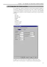
Page 96: ...Function 9 2 Preparation for Communication RS 232C Settings 84 ...
Page 106: ...Function 11 Stand alone Option for SRC520 94 ...
Page 108: ...Maintenance 96 ...
Page 139: ...Maintenance 4 3 Drive Unit Drive Unit 127 4 3 Drive Unit 4 3 1 System Configuration ...


