background image

EPSON Stylus C82

Revision A

PRODUCT DESCRIPTION

Operator Controls

12

1.3  Operator Controls

1.3.1  Operate Switch

Operate switch is located on the control panel.

1.3.2  Control Panel

1.3.2.1  Switches

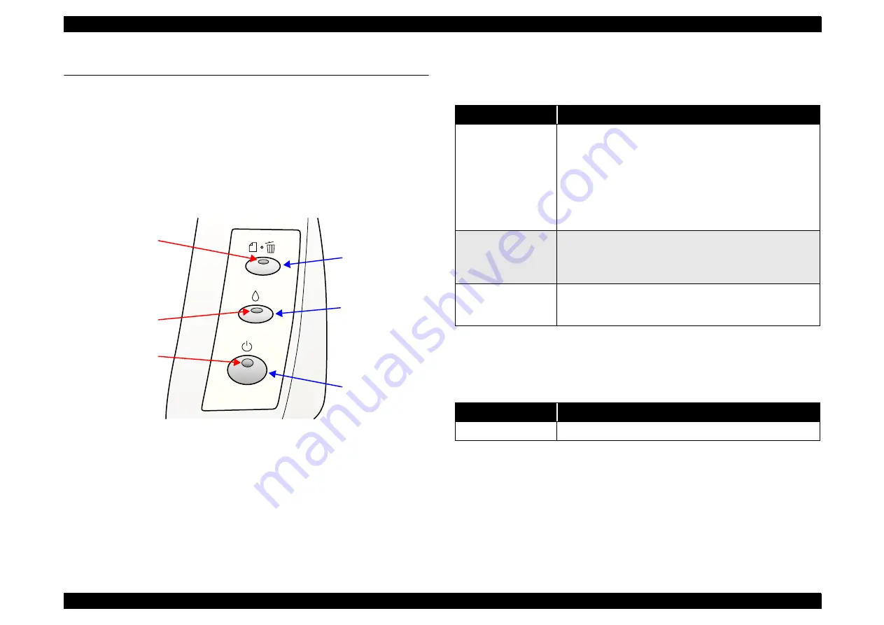
There are 3 non-lock type push switches, and 3 LEDs.

Figure 1-3.  Control panel

1.3.2.2  Indicators

†

Power

Lights when the operate switch is “ON”, and AC power is supplied.

†

Paper Out

Lights during the paper-out condition, and blinks during the paper-jam condition.

†

Ink Out

Lights during no ink condition, and blinks during the ink low condition.

1.3.3  Panel Functions

NOTE:

(*1) 3 seconds is required at the user’s manual.

NOTE:

(*2) This function is not available in printing status.

NOTE:

(*) Status printings prints firmware version, ink counter and nozzle 

check patterns.

NOTE:

The Stylus C82 cannot cancel a maintenance error from the control 
panel. When a maintenance error is generated, use the Adjustment 
Program to clear the counter value.

Ink SW

Paper SW

Power SW

Paper Out LED

Power LED

Ink Out LED

Table 1-4.  Panel functions

Switch

Function

Paper

print cancel

• Loads or ejects the paper.
• When carriage is on the ink check position, move carriage to 

next ink check position or cartridge change position.

• When carriage is on the ink cartridge change position, return 

carriage from ink cartridge change position.

• In the condition of “Double feed error”, recovering from error 

condition, printing is restarted.

• In the condition of printing, cancel the print job.

Ink

• Starts the ink cartridge change sequence. 

(

*

2)

Move the carriage to cartridge change position.

• When carriage is on the ink change position, return carriage 

from ink cartridge change position.

Ink

(Pushing for 2 seconds *

1

)

• Starts the cleaning of head.
• In the condition of “Ink low” or “Ink out” or “No ink cartridge”, 

starts the ink cartridge change sequence.

Table 1-5.  Panel functions with power on

Switch

Pressing with power on function

Paper

Start status printings. 

(

*

1)

Summary of Contents for Stylus C82

Page 1: ...EPSONStylusC82 Color Inkjet Printer SEIJ02003 SERVICE MANUAL ...

Page 2: ...r should any errors be detected SEIKO EPSON would greatly appreciate being informed of them The above not withstanding SEIKO EPSON CORPORATION can assume no responsibility for any errors in this manual or the consequences thereof EPSON is a registered trademark of SEIKO EPSON CORPORATION General Notice Other product names used herein are for identification purpose only and may be trademarks or reg...

Page 3: ...E MUST BE CONNECTED USE EXTREME CAUTION IN WORKING ON POWER SUPPLY AND OTHER ELECTRONIC COMPONENTS 4 WHEN DISASSEMBLING OR ASSEMBLING A PRODUCT MAKE SURE TO WEAR GLOVES TO AVOID INJURIER FROM METAL PARTS WITH SHARP EDGES WARNING 1 REPAIRS ON EPSON PRODUCT SHOULD BE PERFORMED ONLY BY AN EPSON CERTIFIED REPAIR TECHNICIAN 2 MAKE CERTAIN THAT THE SOURCE VOLTAGES IS THE SAME AS THE RATED VOLTAGE LISTED...

Page 4: ...Exploded diagram Electrical circuit boards schematics Symbols Used in this Manual Various symbols are used throughout this manual either to provide additional information on a specific topic or to warn of possible danger present during a procedure or an action Be aware of all symbols when they are used and always read NOTE CAUTION or WARNING messages Indicates an operating or maintenance procedure...

Page 5: ...Revision Status Revision Issued Date Description A July 31 2002 First Release ...

Page 6: ... 1 5 Ink Cartridge 15 1 5 1 Black Ink Cartridge 15 1 5 2 Color Ink Cartridge 15 Chapter 2 OPERATING PRINCIPLES 2 1 Overview 17 2 1 1 Printer Mechanism 17 2 1 2 Carriage Motor Specification 17 2 1 3 Paper Feeding Motor Specification 17 2 1 4 Paper Loading Mechanism New ASF unit 17 2 1 4 1 Drive Process 17 2 1 5 Ink System Mechanism 18 2 1 5 1 Pump Unit Wiper mechanism 18 2 2 Electrical Circuit Oper...

Page 7: ... 6 CR Guide Shaft Carriage Unit Removal 37 4 2 3 7 Ink System Unit Removal 39 4 2 3 8 CR Motor Removal 39 4 2 3 9 PF Motor Removal 40 4 2 3 10 Paper Eject Frame Unit Removal 40 4 2 3 11 EJ Roller Unit Removal 41 4 2 3 12 Front Paper Guide Removal 41 4 2 3 13 Upper Paper Guide Removal 42 4 2 3 14 Rear Paper Guide Removal 42 4 2 3 15 PF Roller Unit Removal 42 Chapter 5 ADJUSTMENT 5 1 Overview 44 5 1...

Page 8: ...C H A P T E R 1 PRODUCTDESCRIPTION ...

Page 9: ...ons This section covers specifications of the printers 1 2 1 Physical Specification Weight 5 2kg without the ink cartridges Dimension 470mm W x 593mm D x 316mm H 1 2 2 Printing Specification Print method On demand ink jet Nozzle configuration Monochrome 180 nozzles Color 59 nozzles x 3 Cyan Magenta Yellow Figure 1 1 Nozzle rear view Print direction Bi direction with logic seeking Print speed Print...

Page 10: ... in sleep mode Approx 0 35W in powered off mode Energy Star compliant Insulation resistance 10M ohms min between AC line and chassis DC 500V Dielectric strength AC 1000V rms 1 minute or AC 1200V rms 1 second between AC line and chassis 220 to 240V version Rated voltage AC 220 to 240V Input voltage range AC 198 to 264V Rated frequency range 50 to 60Hz Input frequency range 49 5 to 60 5Hz Rated curr...

Page 11: ... class B 220 to 240V version Safety standards EN60950 VDE EMI EN55022 CISPR Pub 22 class B AS NZS 3548 class B 1 2 9 Acoustic Noise Level Approx 42dB A According to ISO 7779 1 2 10 CE Marking 220 to 240V version Low voltage directive 73 23 EEC EN60950 EMC directive 89 336 EEC EN55022 class B EN55024 EN61000 3 2 EN61000 3 3 Table 1 3 Environmental Condition Operating Non operating 1 Temperature 10 ...

Page 12: ...e error is generated use the Adjustment Program to clear the counter value Ink SW Paper SW Power SW Paper Out LED Power LED Ink Out LED Table 1 4 Panel functions Switch Function Paper print cancel Loads or ejects the paper When carriage is on the ink check position move carriage to next ink check position or cartridge change position When carriage is on the ink cartridge change position return car...

Page 13: ...ter fails to load a sheet it goes double feed error 1 4 Paper 1 4 1 Paper Handling Reverse feed of more than 9 5mm 0 38 is not allowed 1 4 2 Paper Specification Cut sheet Table 1 6 Printer condition and LED status Printer status Indicators Priority Power Ink out Paper out Power on condition On 11 Ink sequence Blink 7 Ink cartridge change mode Blink 6 Data processing Blink 9 Paper out On 5 Double f...

Page 14: ...3mm 5 x 8 Index card 127mm 203mm 10 x 8 Index card 254mm 203mm Table 1 10 Paper Specification Post cards Paper size Paper width Paper length Post card 100mm 148mm Return post card 200mm 148mm Table 1 11 Character mode Paper size LM Left margin min RM Right margin min TM Top margin min BM Bottom margin min A4 3mm 0 12 3mm 0 12 3mm 0 12 14mm 0 54 Letter 3mm 0 12 9mm 0 35 3mm 0 12 14mm 0 54 B5 3mm 0 ...

Page 15: ...ellow Print capacity 420 pages A4 360 dpi 5 duty each color Ink life 2 years from production date Storage temperature 20oC to 40oC Storage within a month at 40oC 30oC to 40oC Packing storage within a month at 40oC 30oC to 60oC Transit within 120 hours at 60oC and within a month at 40oC Dimension 12 7mm W x 71 2mm D x 66 5mm H NOTE Ink cartridges cannot be refilled Only new cartridges are prepared ...

Page 16: ...C H A P T E R 2 OPERATINGPRINCIPLES ...

Page 17: ...atchet 65 6 but not transmitted to the LD Roller 2 After receiving the paper feed command the Carriage Unit contacts the A or B ASF Trigger Lever 3 At this point the Change Lever extends in the direction of arrow C locking the Clutch mechanism 4 The motion of Combination Gear Ratchet 65 6 is transferred to Clutch Gear 1 5 LD Roller Gear 2 rotates one time LD Roller rotates once and then the LD Rol...

Page 18: ...AIN Board and C486 PSB PSE Board 2 2 1 C486 PSB PSE Board Figure 2 2 C486 PSB PSE Board Block Diagram Table 2 3 PF motor rotational direction Ink system mechanism Directions Functions Counterclockwise 1 Set wiper Draw ink Set CR lock lever Clockwise 1 Reset wiper Release pump Reset CR lock lever 5VDC Line Over Voltage Limitation 42VDCLine Over Voltage Limitation 42VDC Line Drop Limitation 42VDC Li...

Page 19: ...rive Reset regulator IC4 Formed reset signals shown below 1 Dropping 42V line to 36 3V 2 Dropping 5V line to 4 2V D RAM IC5 4 Mbit RAM 2 CAS type 16 bit bus 5V and 3 3V drive provide page access functions EEPROM IC6 1 kbit capacity for default setting or adjusted value Motor Driver IC8 For driving both CR and PF motors PWM control by program timer 5V regulation 42V drive Head Driver 1 IC9 For crea...

Page 20: ... D6 171 D7 166 D8 167 D9 172 D10 1 D11 6 D12 2 D13 173 D14 168 D15 163 MRES 129 NMI 131 RESET 130 HWFLR 36 HWSDATA 39 HWSCLK 30 HWSLAT 31 HWCLK1 33 HWCLK2 34 HWA0 40 to HWA4 44 RST_DCMCU 89 PWM1_MCU 82 PWM2_MCU 87 DATA1_MCU 81 CLK1_MCU 83 DATA2_MCU 86 CLK2_MCU 88 ENCA_PFDCU 54 ENCB_PFDCU 55 SWA1 72 PSC0 69 SW0 57 to SW2 59 LED2 66 to LED0 68 DP 98 DM 99 USBLH 95 ECS 128 ECK 127 EDO 126 EDI 125 A1 ...

Page 21: ...C H A P T E R 3 TROUBLESHOOTING ...

Page 22: ...d could result in an electric shock so carefully avoid this After initial filling of ink has been repeated several times immediate moving or tilting of the printer could result in leaking of ink that has not been completely absorbed by the Waste Ink Pad When initial filling of ink has been repeated several times check the ink remaining in the tip of the Waste Ink Tube and the waste ink not absorbe...

Page 23: ...ad 3 1 1 6 Dot missing 2 When a specific single dot is missing only with color printing and cannot be recovered check whether or not the Stylus C80 Printer Driver is being used With the Stylus C82 59 nozzles are used for each color nozzle so 1 dot will be missing if the Stylus C80 Printer Driver is used Table 3 2 2Dh address Sequence error Address Error Condition Address Error Condition 00h No err...

Page 24: ...C H A P T E R 4 DISASSEMBLYANDASSEMBLY ...

Page 25: ...ns in this manual Wear protective goggles to protect your eyes from ink If ink gets in your eye flush the eye with fresh water and see a doctor immediately Always wear gloves for disassembly and reassembly to avoid iujury from sharp metal edges To protect sensitive microprocessors and circuitry use static discharge equipment such as anti static wrist straps when accessing internal components Never...

Page 26: ... 2 P 32 CR Motor Removal 4 2 3 8 P 39 PF Motor Removal 4 2 3 9 P 40 ASF Unit Removal 4 2 3 1 P 32 CR Guide Shaft Carriage Unit Removal 4 2 3 6 P 37 PF Roller Unit Removal 4 2 3 15 P 42 Use the flowchart to determine the shortest procedure for the unit to be replaced then disassemble the printer by following that procedure The step for the unit or discrete part within the broken line is not the sho...

Page 27: ...ng Upper Housing follow the order shown below to remove 1 1 screw C B S 3x6 and 2 FFC from C486 PNL Board Then remove the Upper Housing Figure 4 4 Upper Housing Removal 3 4 2 1 2 Panel Housing C486 PNL Board Removal 1 Remove Upper Housing See Section 4 2 1 1 2 While pressing inward the 2 hooks holding the Panel Housing remove the Panel Housing by pushing it in the direction of arrow A Figure 4 5 P...

Page 28: ... Cartridge from the Carriage Unit Figure 4 7 Printhead Removal 1 3 Remove 2 screws C B P P4 3x8 holding the Fastener Head then remove the Fastener Head in the direction of arrow A Figure 4 8 Printhead Removal 2 4 Push Carriage Lock Lever forward then shift Carriage Unit to the left side 5 Use the order shown below to release 4 hooks then remove Cable Head Holder from Carriage Unit in upward direct...

Page 29: ... C B S 3x8 1 holding Printer Mechanism Figure 4 12 Lower Housing Printer Mechanism Removal 1 Printhead 1 2 Hook Hook FFCs Sponge Printhead C A U T I O N When the FFC has been replaced be sure to attach sponge as shown in lower left diagram Because double sided tape is attached to FFC service parts simply installing sponge is sufficient A D J U S T M E N T R E Q U I R E D When removing or replacing...

Page 30: ...emove from Lower Housing 4 2 2 Board Removal 4 2 2 1 C486 Main Board Removal 1 Remove Printer Mechanism See Section 4 2 1 4 2 Remove all cables from C486 Main Board and peel off acetate tape in 2 places Figure 4 14 Main Board Removal 1 FFC Disconnect Left Rear Side Center Rear Side Inner Side AC Cable Cover Right Front Side C Ink tube Hook Hook A A B Retainer D Hook W A R N I N G Make sure the tip...

Page 31: ...nter Front Side Printer Rear Side Blue Line Pin 1 W A R N I N G When C486 Main Board has been replaced by a service part the installation screw holes do not have threads as shown below When installing C486 Main Board to the Printer Mechanism metal chips that are formed in the process can become a source for shorting the printer For this reason use a brush to clean 2 places in the order shown below...

Page 32: ...ion 4 2 1 4 2 Disconnect connector CN4 from C486 Main Board unfasten it from the wrapped location then remove the CN4 cable by pulling it through the slot in the ASF Unit 3 Remove 2 screws C B S P4 3x8 holding the ASF Unit Figure 4 19 ASF Unit Removal 1 4 Remove 1 screw C B S 3x6 holding the LD Roller Cover and then shift LD Roller Cover in direction of arrow A Figure 4 20 ASF Unit Removal 2 A D J...

Page 33: ...e Lever 4 Combination Gear Ratchet 65 6 Figure 4 22 ASF Unit Disassembly 1 4 Release Extension Spring 1 67 from hooks on ASF Frame and ASF Trigger Lever then remove spring C A U T I O N Be careful because pulling strongly on Pump Frame can cause it to break When installing ASF Unit be sure to install it while Main Board and PSB PSE Board are not installed If this procedure is ignored the Pump Fram...

Page 34: ...the ASF Frame toward the outside follow the order shown below to remove LD Roller Shaft Figure 4 25 ASF Unit Disassembly 4 9 Release Extension Spring 2 25 from hooks on ASF Frame and Retard Roller Holder then remove spring 10 Pull the protrusion of the Retard Roller Holder fastened to the ASF Frame away from the ASF Frame in the direction of the arrow for one side and then the other Then remove Re...

Page 35: ... Sensor Holder then remove PE Sensor from the PE Sensor Holder 5 Follow the order shown below to remove the PE Lever along with Torsion Spring 0 28 from the PE Sensor Holder Figure 4 29 PE Sensor PE Sensor Holder PE Lever Removal 2 ASF Unit Assembly Points 1 Set Clutch Spring when assembling Clutch and Clutch Gear 2 Position Paper Back Support Lever when setting the Paper Back Cam to LD Roller Sha...

Page 36: ...ioning because the Film type and Plastic type are completely interchangeable PF Roller Unit and Printer Mechanism service parts are continuing with the Film type regardless of the developments 3 After patent concerns are settled in America both new products and service parts PF Roller Unit and Printer Mechanism will use the new Plastic type 4 Points that should be considered for repair are shown b...

Page 37: ... Pulley Driven Holder in direction of arrow A the remove it in direction of arrow B Figure 4 35 CR Guide Shaft Carriage Unit Removal 1 4 Follow order shown in Figure 4 36 lower right photo to remove these items from the Printer Mechanism 1 Spacer 2 PG Lever 2 Torsion Spring 67 78 3 Leaf Spring 4 1 Screw C B S P4 3x6 5 Bushing 5 Follow order shown in Figure 4 36 lower left photo to remove these ite...

Page 38: ... 3 Carriage Unit Right Side Left Side Spacer PG lever Bush Torsion spring 67 78 Leaf spring 1 7 Bush Spacer C B S P4 3x6 6 1kgf cm CR Guide Shaft 9 2 2 5 4 3 Removal Direction 6 8 Hooks 10 C D C B S P4 3x6 6 1kgf cm Slot C A U T I O N Be careful when installing the Bushings at each side of the Printer Mechanism because the Left Bushing and Right Bushing have different shapes See Figure 4 36 Leaf S...

Page 39: ...hanism 6 Follow the order shown above to remove the 0 Digit Flashing Box from the Printer Mechanism 4 2 3 8 CR Motor Removal 1 Remove Printer Mechanism See Section 4 2 1 4 2 Disconnect CN14 connector from C486 Main Board 3 Remove 1 screw C C 3x4 holding CR Motor then remove CR Motor Figure 4 41 CR Motor Removal 2 C B S 3x6 8 1kgf cm Ink System Frame Ink System Unit 0 Digit Flashing Box Push lift 4...

Page 40: ...S T M E N T R E Q U I R E D When replacing the CR Motor the adjustments are necessary Refer to Chapter 5 Adjustment for the adjustment procedure PF Motor C C 3x4 3 1kgf cm 1 2 No label side Left Side Installation of screws holding PF Motor 1 Follow order shown in lower left diagram to set screws temporarily 2 Pull PF Motor in direction shown by arrow in lower left diagram then while maintaining te...

Page 41: ...12 Front Paper Guide Removal 1 Remove EJ Roller Unit See Section 4 2 3 11 2 Remove 2 screws C B S 3x6 holding Front Paper Guide 3 Remove Front Paper Guide upwards while being careful that the Front Paper Guide hook at the left side does not touch Spur Gear 28 8 Figure 4 46 Front Paper Guide Removal When installing EJ Roller Unit be careful about the direction of the CR Lock Figure 4 45 CR Lock Dir...

Page 42: ...e to PF Roller Unit then remove Rear Paper Guide by pushing it in direction of arrow B Figure 4 48 Rear Paper Guide Removal 4 2 3 15 PF Roller Unit Removal 1 Remove Rear Paper Guide See Section 4 2 3 14 2 Use tweezers to remove leg of Compression Spring 4 89 from Printer Mechanism 3 Use tweezers to release left and right Bushing 8 fastening PF Roller Unit to Printer Mechanism then allow the PF Rol...

Page 43: ...C H A P T E R 5 ADJUSTMENT ...

Page 44: ...ts EEPROM initialization Performed after circuit board replacement regardless of result from Backup try described above This operation allows the firmware to recognize differences between Japanese made parts and foreign made parts and optimizes the ID check performed between the main circuit board and the ink cartridge Head ID input Performed after printhead and main board replacement If this is n...

Page 45: ...g 1 Used for first operation check with recycled parts 2 Used to switch to adjustment for checking correct printing after ink charging following printhead replacement 3 Used for print check after completed repairs This function checks printing in each print mode and confirms absence of printing problems Check points for each print pattern are explained in the adjustment program Maintenance Head cl...

Page 46: ...C H A P T E R 6 MAINTENANCE ...

Page 47: ...g actions to clear the error Head Cleaning 4 methods of recovering Dot Missing are shown below 1 Press Ink Switch on control panel 2 Execute cleaning with printer driver 3 Execute strong cleaning with Adjustment Program 4 Execute Ink Charge with Adjustment Program Maintenance Error Clear Maintenance errors cannot be cleared from the control panel which is different from previous models They can on...

Page 48: ...ging any parts use the Flux Dispenser 1049533 to apply one coat to specified areas Because it is necessary to apply G 46 when replacing old parts with new parts soak the parts in G 46 as shown in the photograph on page 50 Table 6 2 Lubrication Points Fig No Lubrication Point Type Remarks 6 1 Lubrication Point Driven Roller x 8 Lubrication Type G 46 Lubrication Amount Soak in basin containing G 46 ...

Page 49: ...ler Use a brush to apply it 6 7 Lubrication Point Carriage Unit Shaft Socket Lubrication Type G 63 Lubrication Amount Shaft Socket Inner Side Use a brush to apply it Table 6 2 Lubrication Points Fig No Lubrication Point Type Remarks 6 8 Lubrication Point Pulley Driven Holder Lubrication Type G 26 Lubrication Amount φ1 x 2mm x 4points Use a brush to apply it 6 9 Lubrication Point Main Frame Upper P...

Page 50: ...gure 6 3 Paper Back Support Lever Figure 6 4 LD Roller Shaft Figure 6 5 Clutch Gear Figure 6 6 PF Roller G 46 G 26 G 46 No 1 No 2 G 46 G 46 G 46 G 26 Figure 6 7 Carriage Unit Figure 6 8 Pulley Driven Holder Figure 6 9 Main Frame Figure 6 10 ASF Unit Figure 6 11 ASF Trigger Lever G 63 G 26 G 26 G 26 G 26 G 26 ...

Page 51: ...C H A P T E R 7 APPENDIX ...

Page 52: ...with the Power supply board Table 7 8 CN20 For connection with the Panel board Table 7 9 Table 7 2 CN4 PE sensor Pin Signal Name I O Function 1 PE In Sensor detect signal 2 GND Ground 3 PEV Sensor power supply Table 7 3 CN8 Printhead Pin Signal Name I O Function 1 GND Ground 2 COM Out Head drive pulse trapezoid waveform 3 VBS Out Power for nozzle selector IC 4 COM Out Head drive pulse trapezoid wa...

Page 53: ...p 16 NCHG Out Source signal for driving Trapezoidal wave form Table 7 3 CN8 Printhead Pin Signal Name I O Function 17 GND Ground 18 COM Out Head drive pulse trapezoid waveform 19 VBS Out Power for nozzle selector IC 20 COM Out Head drive pulse trapezoid waveform 21 VBS Out Power for nozzle selector IC 22 COM Out Head drive pulse trapezoid waveform 23 VBS Out Power for nozzle selector IC 24 COM Out...

Page 54: ...Out LED drive signal 0 6 GND Ground 7 SW0 In Panel switch on off 0 8 VCC Out Power for the panel board Table 7 10 EEPROM address map Address Explanation Setting QPIT setting Factory settings 00H Password 0FH 01H 5AH 02H Ink counter A 00H 00H 03H 04H Ink counter R0 00H 00H 05H 06H Ink counter R80 00H 00H 07H 08H Ink flag1 bit7 Reserved bit6 CSIC chg seq2 required bit5 In manual Cleaning seq bit4 In...

Page 55: ...ff 00H 01H Table 7 10 EEPROM address map continued Address Explanation Setting QPIT setting Factory settings 2AH I F control flags bit7 Reserved bit6 Reserved bit5 Reserved bit4 Reserved bit3 ECP speed 0 Fast 1 Slow bit2 Compatibility speed 0 Fast 1 Slow bit1 ECP mode 0 Off 1 On bit0 IEEE1284 mode 0 On 1 Off 00H 00H 2BH CR duty Data for heat 00H 00H 2CH PF duty Data for hear 00H 00H 2DH Fatal Erro...

Page 56: ...SD3 Color 60 n 60 00H 1 3DH Bi D adjustment for VSD2 Black 60 n 60 00H 1 Table 7 10 EEPROM address map continued Address Explanation Setting QPIT setting Factory settings 3EH Bi D adjustment for VSD2 Color 60 n 60 00H 1 3FH Bi D adjustment for VSD1 Black 60 n 60 00H 1 40H Password 0FH 41H 5AH 42H Head actuator rank ID for Vh1L 00H 1 43H Head actuator rank ID for Vh2L 00H 1 44H Head actuator rank I...

Page 57: ...ded diagram is not provided in the Stylus C82 Service Manual If consultation of an exploded diagram is necessary see the exploded diagram attached to the Stylus C82 Parts List 53H 64H USB ID 00H 00H 1 1 65H 7EH Model name 00H 00H 7FH Market ID 0 STD 1 Japan 2 Custom 00H 00H World 01H Japan Table 7 10 EEPROM address map continued Address Explanation Setting QPIT setting Factory settings ...

Page 58: ...EPSON Stylus C82 Revision A APPENDIX Electrical Circuits 58 7 3 Electrical Circuits ...

Page 59: ...EPSON Stylus C82 Revision A APPENDIX Electrical Circuits 59 ...

Page 60: ...EPSON Stylus C82 Revision A APPENDIX Electrical Circuits 60 ...

Page 61: ...EPSON Stylus C82 Revision A APPENDIX Electrical Circuits 61 ...

Reviews: