EPSON Stylus COLOR 860/1160
Revision C
Operating Principles
Electrical Circuit Operating Principles
40
2.2 Electrical Circuit Operating Principles
The electric circuit of the Stylus COLOR 860/1160 is composed of the following
boards.
o
Main board:
C298MAIN (Stylus COLOR 860/1160)
o
Power supply board: C298PSB/PSE (Stylus COLOR 860/1160)
o
Panel board:
C298PNL (Stylus COLOR 860)
C304PNL (Stylus COLOR 1160)
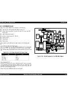
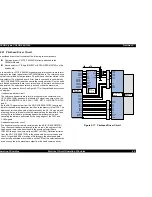
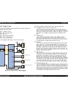
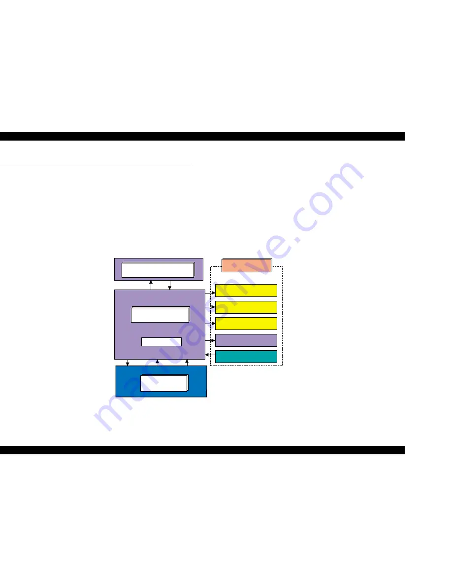
Refer to Figure 2-13 for the major connection of the three boards and their
roles.
Figure 2-14. Electric Circuit of Stylus COLOR 860/1100
C 2 9 8 P S B / P S E
B o a r d
+ 4 2 V D C
+ 5 V D C
C 2 9 8 M A I N B o a r d
P r i n t e r M e c h a n i s m
C R M o t o r
P F M o t o r
H e a d D r i v e r B o a r d
S e v e r a l S e n s o r s
P o w e r o f f
3 . 3 V R e g u l a t o r
C 2 9 8 P N L B o a r d ( S C 8 6 0 )
C 3 0 4 P N L B o a r d ( S C 1 1 6 0 )
A S F / P u m p M o t o r
Summary of Contents for Stylus COLOR 1160
Page 8: ...C H A P T E R PRODUCTDESCRIPTION ...
Page 28: ...C H A P T E R OPERATINGPRINCIPLES ...
Page 53: ...C H A P T E R TROUBLESHOOTING ...
Page 74: ...C H A P T E R DISASSEMBLYANDASSEMBLY ...
Page 116: ...C H A P T E R ADJUSTMENT ...
Page 150: ...C H A P T E R MAINTENANCE ...
Page 160: ...APPENDIX C H A P T E R ...


