EPSON Stylus COLOR 860/1160
Revision C
Disassembly and Assembly
Disassembly Procedures
83
4.2.3 Removing the Operation Panel
The panel board equipped with each printer is as follows:
- Stylus COLOR 860:
C298PNL
- Stylus COLOR 1160: C304PNL
1.
Remove the Upper Housing. (Refer to Section 4.2.1.)
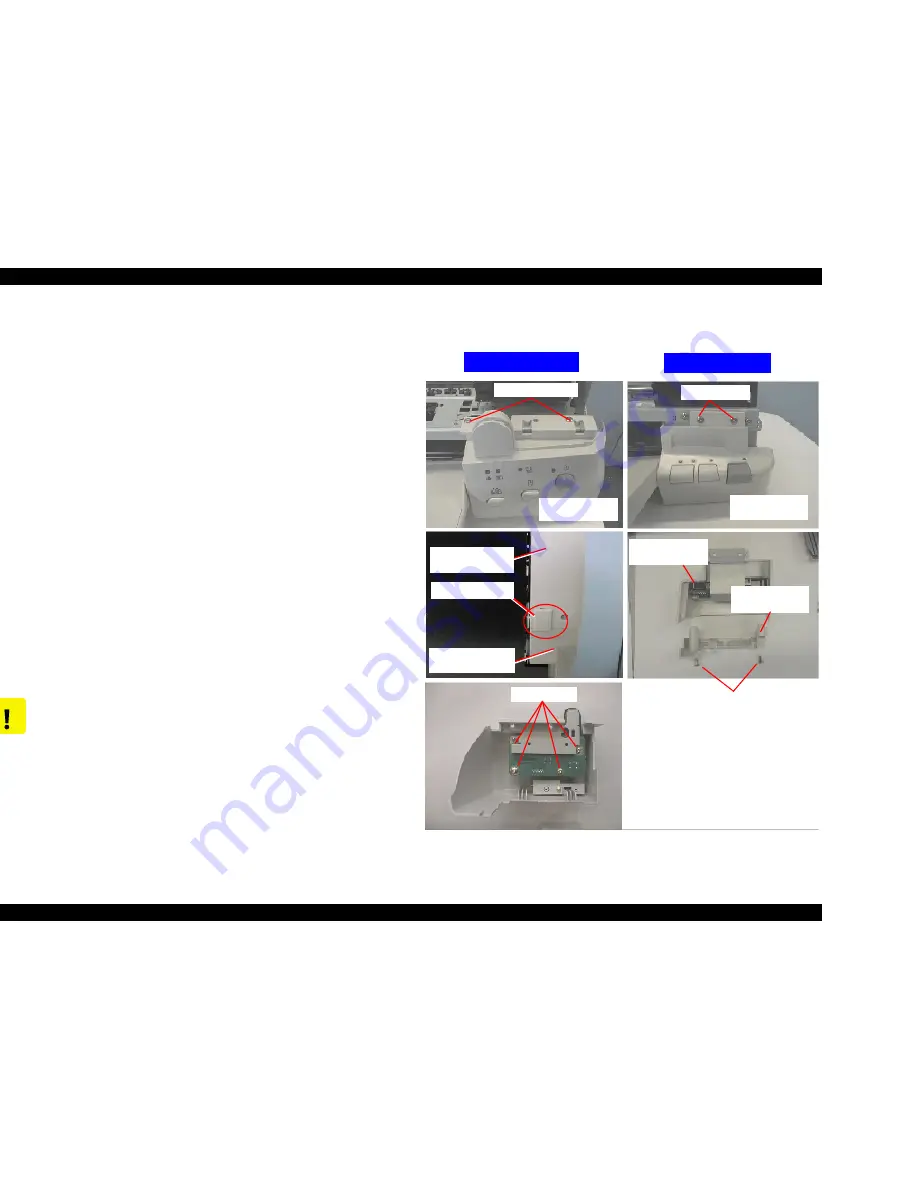
2) Remove two screws (No.1) securing the Operation Panel Assembly.
Then:
Stylus COLOR 860
: Disconnect the Operation Panel Assembly from the
Printer Mechanism.
Stylus COLOR 1160
: Release the joint for the protrusion on the Operation
Panel and the gutter of the Right Sub Frame, and remove the Operation
Panel Assembly from the Printer Mechanism
Refer to Figure 4-6. The left column’s figures show the Stylus COLOR
1160 and the ones in the right column show the Stylus COLOR 860.
3)
Stylus COLOR 860
: Remove two screws (No.3) and detach the Sub Right
Panel Housing from the Operation Panel Assembly.
Stylus COLOR 1160
: Remove four screws (No.3) securing the C304PNL
board. Note the Stylus COLOR 1160 does not have a Sub Right Panel
Housing.
4) Remove the Panel Shield Plate and the C298PNL/C304PNL board from
the Operation Panel Assembly.
5) Disconnect the Panel FFC from the connector on the C298PNL/C304PNL
board.
Figure 4-6. Removing the Operation Panel
C A U T I O N
Removing the Operation Panel Assembly also separates the
stacker assembly from the Printer Mechanism, since the
Stacker Assembly is held with Operation Panel.
No.1 Screws
Operation Panel
Assembly
Sub Right
Panel Housing
SC860
Operation Panel
SC1160
Operation Panel
No.3 Screws
No.3 Screws
Stylus COLOR 1160
Stylus COLOR 860
No.1 Screws
SC1160
Operation Panel
Jointing position
SC1160
Sub Right Frame
Summary of Contents for Stylus COLOR 1160
Page 8: ...C H A P T E R PRODUCTDESCRIPTION ...
Page 28: ...C H A P T E R OPERATINGPRINCIPLES ...
Page 53: ...C H A P T E R TROUBLESHOOTING ...
Page 74: ...C H A P T E R DISASSEMBLYANDASSEMBLY ...
Page 116: ...C H A P T E R ADJUSTMENT ...
Page 150: ...C H A P T E R MAINTENANCE ...
Page 160: ...APPENDIX C H A P T E R ...

